SERVICE MANUAL UPDATE SEC. 6A5 (VFV) VARIABLE FUEL VEHICLE

Subject: VARIABLE FUEL VEHICLE (VFV) ONLY SUPPLEMENTAL MANUAL REVISION
Model and Year: 1991 LUMINA WITH 3.1 L ENGINE
This bulletin revises the 1991 Chevrolet Lumina Service Manual Supplement Variable Fuel Vehicle (VFV) ONLY. This information applies to the following sections:
ENGINES (SECTION 6A5). Revised torque specifications and text changes found on Pages 6A5-16, 6A5-17, 6A5-18, 6A5-19, 6A5-25, 6A5-30, 6A5-33, 6A5-39, 6A5-42, 6A5-44, 6A5-45, 6A5-48, 6A5-49, 6A5-50, 6A5-52, and 6A5-55.
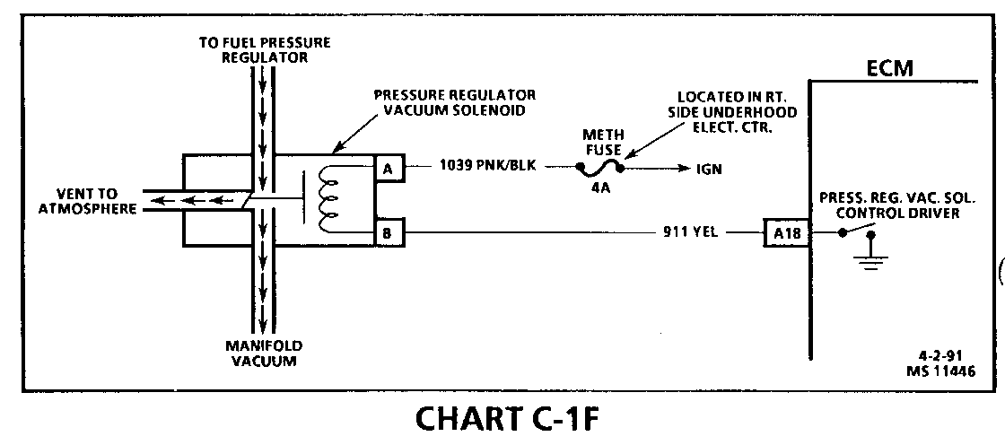
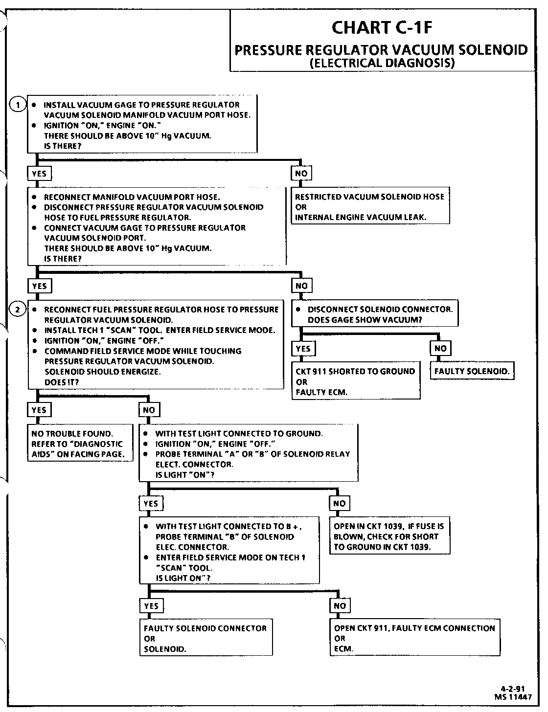
DRIVEABILITY AND EMISSIONS (SECTION 6E3-C1). Adding CHART C-1F (Pressure Regulator Vacuum Solenoid) Facing Page and Diagnostic Chart on pages 6E3-C1-20 and 6E3-C1-21.
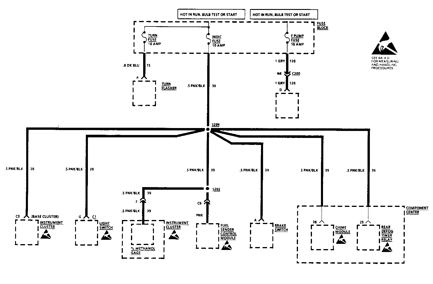
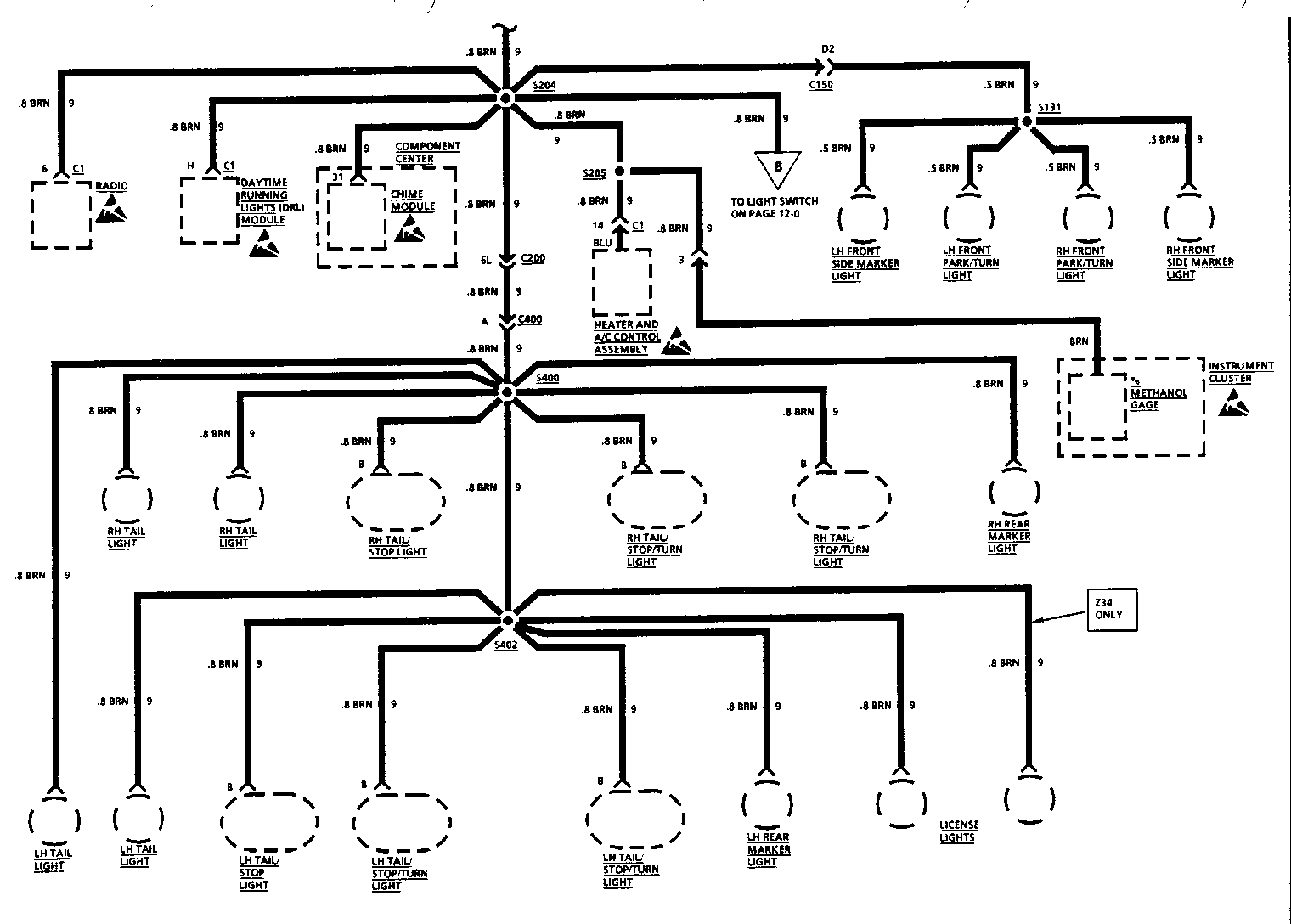
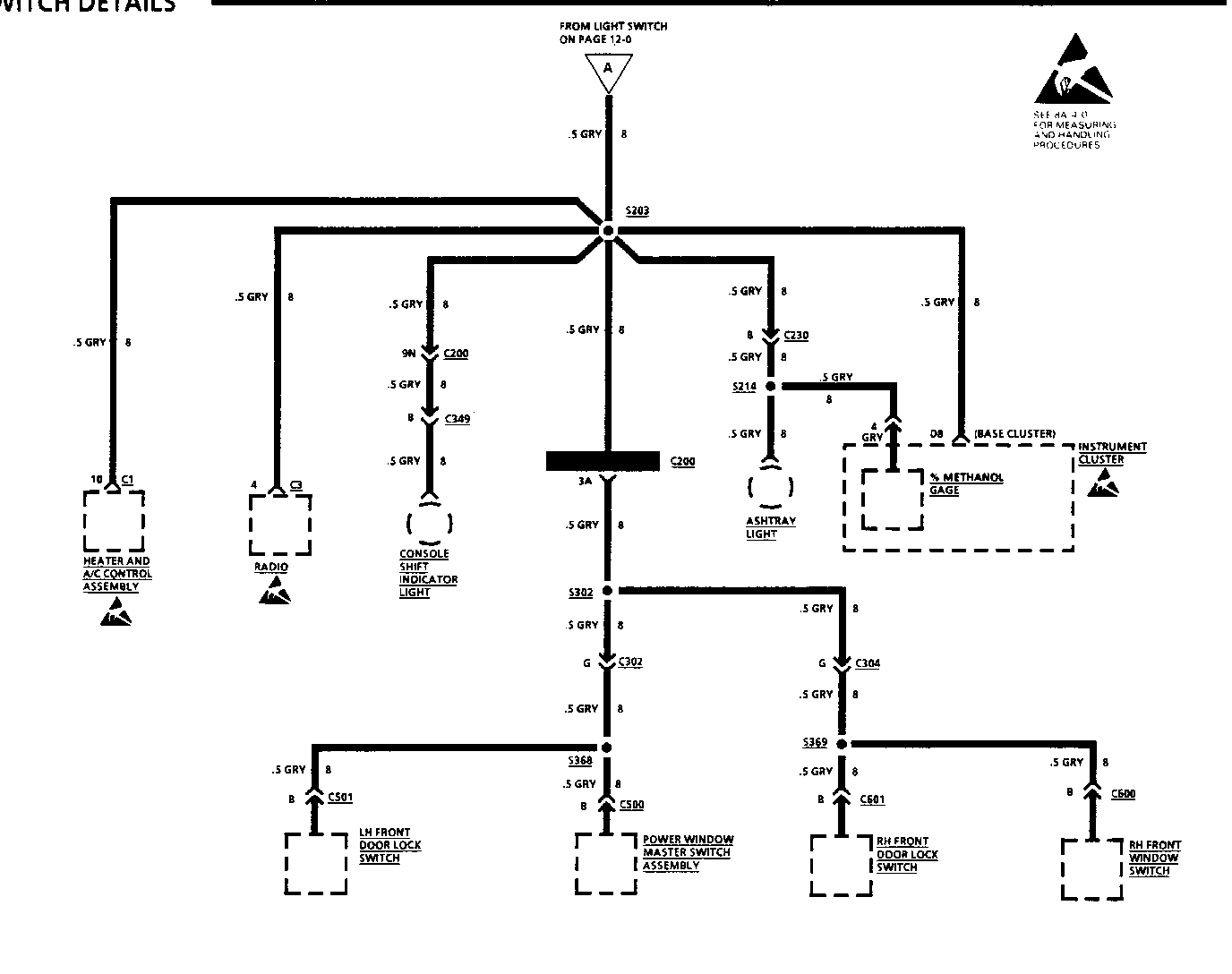
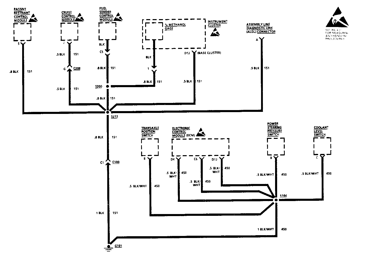
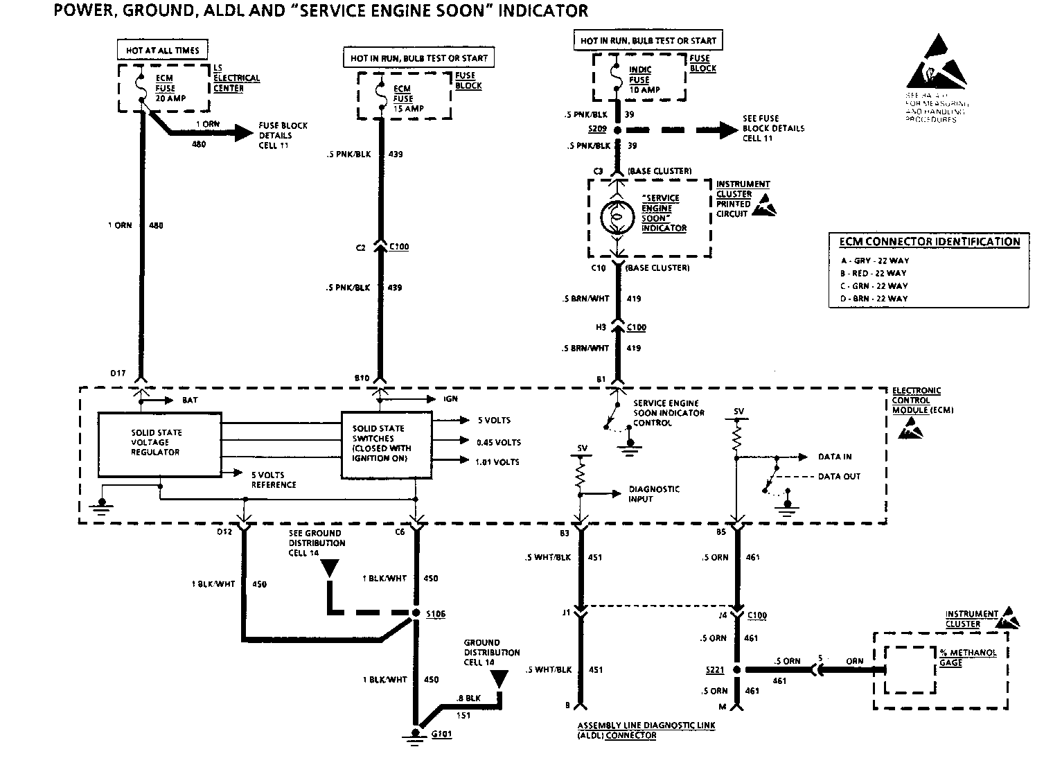
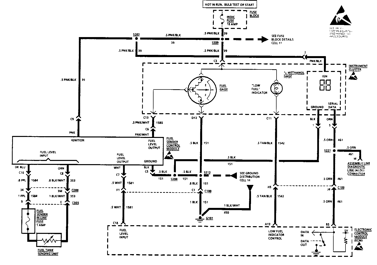
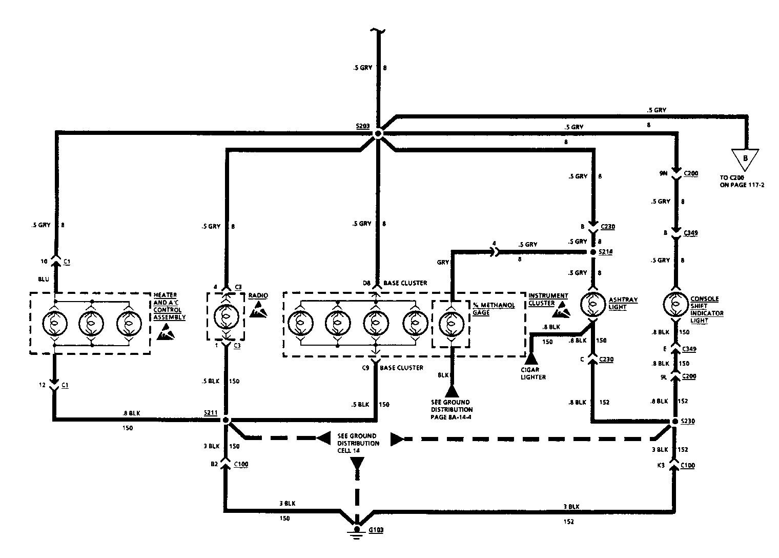
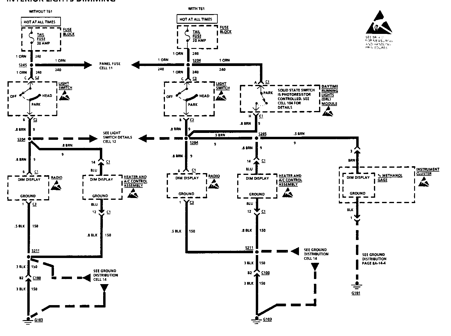
ELECTRICAL DIAGNOSIS (SECTION 8A). The following pages reflect changes to the circuitry due to the addition of Methanol Percent Gage added to Up Level Cluster: 8A-11-1, 8A-12-1, 8A-12-2, 8A-14-4, 8A-20-0, 8A-80-0, 8A-80-1, 8A-80-4, 8A-117-1, and 8A-117-3.
CHART C-1 F PRESSURE REGULATOR VACUUM SOLENOID (ELECTRICAL DIAGNOSIS)
Circuit Description:
The Variable Fuel Vehicle uses a pressure regulator vacuum solenoid to control fuel pressure during hot restarts. The solenoid, when commanded by the ECM, will vent the vacuum to atmosphere. This will allow the fuel pressure regulator to put out the maximum amount of fuel for a calibrated time only. The conditions that determine if the solenoid will be activated depends on the amount of methanol (M-85) in the fuel, along with coolant and fuel temperature. This eliminates any vapor lock due to the alcohol in the fuel.
Test Description: Number(s) below refer to circled number(s) on the diagnostic chart.
1. If there is no vacuum available to the solenoid, fuel pressure regulator will be at maximum fuel pressure.
2. When the Tech 1 "Scan" tool is in field service mode, pressure regulator vacuum solenoid control driver will close, which should energize the solenoid, you can feel the solenoid click when energized.
Diagnostic Aids:
If the original complaint was hard starting when the vehicle is hot and the pressure regulator vacuum solenoid is OK, refer to "Symptoms," Section "6E3-B" of the service manual.
16. Plenum, refer to DRIVEABILITY AND EMISSIONS (SECTION 6E3-C2).
[!] Important o Relieve fuel pressure as specified in ENGINE FUEL (SECTION 6C).
17. Fuel lines from fuel rail and lines from retainer. o Set lines aside. 18. Fuel injector electrical connectors. 19. Fuel rail, refer to DRIVEABILITY AND EMISSIONS (SECTION 6E3-C2). 20. Serpentine belt, refer to "Serpentine Drive Belt" in this section. 21. Power steering lines at generator bracket. 22. Rear generator brace, generator, generator bracket. Refer to CHARGING SYSTEM (SECTION 6D3). 23. Engine lift bracket. 24. Power steering pump (support pump aside), refer to POWER STEERING PUMP AND GEAR (SECTION 3B1). 25. Spark plug wires from plugs. o Set wires aside. 26. Heater hose from coolant bypass pipe. 27. Coolant bypass pipe at water pump and nut at cylinder head. o Set coolant bypass pipe aside. 28. Front and rear valve cover, refer to "Valve Covers" in this section. 29. Fasteners from brackets retaining heater pipe. 30. Heater pipe at intake. 31. Upper radiator hose. 32. Intake manifold bolts.
[!] Important o Retain Belleville washers in same orientation on 4 center bolts.
33. Loosen intake rocker arm nuts enough to access pushrods. 34. Intake pushrods. o Intake and exhaust pushrods are different lengths with the exhaust pushrod being the longer of the two. Intake pushrods are marked orange; and are 6 inches long; exhaust pushrods are marked blue and are 6-3/8 inches long. 35. Intake gasket. o Inspect o Flatness of inlet flanges.
[ ] Install or Connect
1. Place a 2-3 mm bead of GM RTV sealer p/n 1052917 (or equivalent) on each ridge where the front and rear of the intake manifold contact the block. 2. Intake manifold gasket. 3. Intake pushrods. o Intake pushrods are marked orange and are 6 inches long. o Exhaust pushrods are marked blue and are 6- 3/8 inches long. o Make sure pushrods seat in lifter. 4. Rocker arm nuts.
[ ] Tighten o Rocker arm nuts to 25 N-m (18 lb.ft.).
5. Intake manifold. 6. Intake manifold bolts.
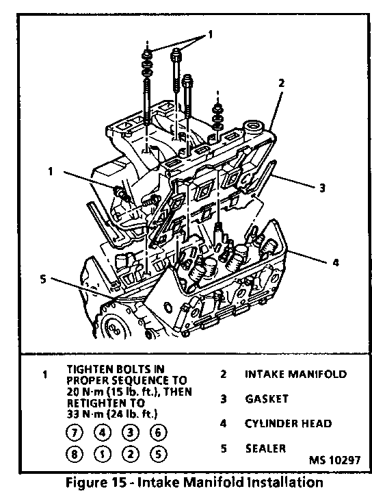
[ ] Tighten o Intake manifold bolts in proper sequence refer to Figure 10.
7. Upper radiator hose. 8. Heater pipe at intake. 9. Fasteners to brackets retaining heater pipe. 10. Front and rear valve covers, refer to "Valve Covers" in this section. 11. Coolant bypass pipe to water pump.
[ ] Tighten o Bolts to 10 N-m (89lb.in.).
12. Nut retaining bypass pipe to cylinder head.
[ ] Tighten o Nut to 25 N.m (18 lb.ft.).
13. Heater hose to coolant bypass pipe. 14. Spark plug wire to plugs. 15. Power steering pump, refer to POWER STEERING PUMP AND GEAR (SECTION 3B1) 16. Generator bracket, and generator, generator brace. Refer to CHARGING SYSTEM (SECTION 6D3). 17. Power steering lines to generator bracket. 18. Serpentine belt; refer to "Serpentine Drive Belt" in this section. 19. Fuel rail, refer to DRIVEABILITY AND EMISSIONS (SECTION 6E3). 20. Fuel injector electrical connectors. 21. Fuel lines to fuel rail and fuel lines to retainer. Refer to DRIVEABILITY AND EMISSIONS (SECTION 6E3-C2). 22. Plenum, refer to DRIVEABILITY AND EMISSIONS (SECTION 6E3-C2) 23. Spark plug harness to plenum. 24. EGR adaptor and valve to plenum, refer to DRIVEABILITY AND EMISSIONS (SECTION 6E3-C7). 25. Throttle body, refer to DRIVEABILITY AND EMISSIONS (SECTION 6E3-C2). 26. Electrical connectors to TPS, IAC, EGR and CTS. 27. Throttle and detent cable bracket. 28. Bracket holding MAP sensor and purge solenoid. 29. Electrical and vacuum connections at MAP and purge solenoid. 30. Cable bracket and retaining cover at plenum. 31. Brake vacuum pipe at plenum. 32. Cables at throttle body. 33. Negative battery cable. 34. Air cleaner assembly. 35. Intake duct to throttle body. 36. IAT sensor electrical connector. 37. Fill cooling system, refer to COOLING AND RADIATOR (SECTION 6B). 38. Perform idle learn procedure, refer to DRIVEABILITY AND EMISSIONS (SECTION 6E3-C2).
[ ] Inspect o Proper fluid levels. o For leaks. o Completion of repair.
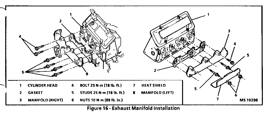
EXHAUST MANIFOLDS
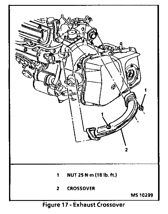
Figures 16 and 17 Left Side (Front)
[ ] Remove or Disconnect
1. IAT sensor electrical connector. 2. Intake duct at throttle body. 3. Air cleaner assembly. 4. Negative battery cable. 5. Coolant recovery bottle, refer to COOLING AND RADIATOR (SECTION 6B). 6. Serpentine belt, refer to "Serpentine Drive Belt" in this section. 7. A/C compressor, refer to AIR CONDITIONING (SECTION 1B). 8. Right side torque strut. 9. A/C and torque strut mounting bracket. 10. Heat shield. 11. Exhaust crossover pipe at manifold, refer to EXHAUST SYSTEM (SECTION 6F). 12. Exhaust manifold bolts. 13. Exhaust manifold.
[ ] Clean o Mating surfaces at cylinder head and manifold.
[ ] Install or Connect 1. Exhaust manifold gasket. 2. Exhaust manifold. 3. Loosely install manifold bolts. 4. Exhaust crossover pipe to manifold, refer to EXHAUST SYSTEM (SECTION 6F). 5. Exhaust manifold bolts.
[ ] Tighten o Bolts to 25 N-m (18 lb.ft.).
6. Heat shield.
[ ] Tighten o Nuts to 10 N-m (89 lb. in.).
7. A/C and torque strut mounting bracket. 8. Right side torque strut. 9. A/C compressor, refer to AIR CONDITIONING (SECTION 1B). 10. Serpentine belt, refer to "Serpentine Drive Belt" in this section. 11. Coolant recovery bottle, refer to COOLING AND RADIATOR (SECTION 6B). 12. Negative battery cable. Refer to "Idle Learn Procedure in DRIVEABILITY AND EMISSIONS (SECTION 6E3-C2).
[ ] Tighten o Bolt to 15 N.m (11 lb.ft.).
13. Air cleaner assembly. 14. Intake duct to throttle body. 15. IAT sensor electrical connector. 16. Perform idle learn procedure, refer to DRIVEABILITY AND EMISSIONS (SECTION 6E3-C2).
Right Side (Rear) Figure 16 and 17
[ ] Remove or Disconnect
1. IAT sensor electrical connector. 2. Intake duct at throttle body. 3. Air cleaner assembly. 4. Negative battery cable. 5. Raise vehicle and suitable support. Refer to GENERAL INFORMATION (SECTION 0A). 6. Exhaust pipe at crossover, refer to EXHAUST SYSTEM (SECTION 6F). 7. Coolant recovery bottle, refer to COOLING AND RADIATOR (SECTION 6B). 8. Torque struts at engine. 9. Rotate engine. Refer to "Rotating Engine" in this section. 10. Heat shield. 11. Crossover at manifold. 12. Accelerator and T.V. cables. 13. Accelerator and T.V. cable bracket at plenum. 14. Exhaust manifold bolts. 15. Exhaust manifold.
[ ] Clean o Mating surfaces at cylinder head and manifold.
[ ] Install or Connect
1. Exhaust manifold gasket. 2. Exhaust manifold. 3. Loosely install manifold bolts. 4. Crossover at manifold. 5. Exhaust manifold bolts.
[ ] Tighten o Bolts to 25 N.m (18 lb.ft.).
6. Accelerator and T.V. cable bracket at plenum. 7. Accelerator and T.V. cables. 8. Return engine to proper position, refer to "Rotating Engine" in this section. 9. Coolant recovery bottle, refer to COOLING AN RADIATOR (SECTION 6B). 10. Torque struts. 11. Raise vehicle and suitably support. Refer to GENERAL INFORMATION (SECTION 0-A). 12. Exhaust pipe to crossover, refer to EXHAUST SYSTEM (SECTION 6F). o Lower vehicle. 13. Negative battery cable. Refer to "Idle Learn Procedure" in DRIVEABILITY AND EMISSIONS (SECTION 6E3-C2).
[ ] Tighten o Bolt to 15N-m (11 lb.ft.).
14. Air cleaner assembly. 15. Intake duct to throttle body. 16. IAT sensor electrical connector. 17. Perform Idle Learn Procedure, refer to DRIVEABILITY AND EMISSIONS (SECTION 6E3-C2).
[ ] Inspect o For exhaust leaks. o Completion of repair.
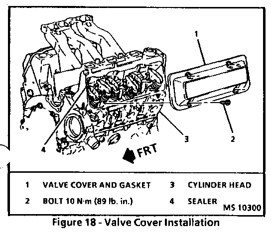
VALVE COVERS Figure 18
Left Side (Front) [ ] Remove or Disconnect
1. Drain coolant, refer to COOLING AND RADIATOR (SECTION 6B). 2. IAT sensor electrical connector. 3. Intake duct at throttle body. 4. Air cleaner assembly. 5. Negative battery cable. 6. Secondary cooling fan, refer to COOLING AND RADIATOR (SECTION 6B). 7. Ignition wire clamps from coolant bypass pipe. 8. Heater hose from bypass pipe. 9. Nut retaining bypass pipe at cylinder head. 10. Bypass pipe at water pump. o Set bypass pipe aside. 11. Air inlet tube from valve cover. 12. Spark plug harness at plenum. 13. Valve cover.
[!] Important If cover adheres to cylinder head, remove by bumping end of valve cover with palm of hand or soft rubber mallet.
[ ] Clean Sealing surface on cylinder head and valve cover with degreaser.
[ ] Install or Connect
1. New gasket and new bolt grommets. o Make sure gasket is seated properly in valve cover groove. 2. GM sealer p/n 1052917 (or equivalent) in notch (Figure 18). 3. Valve cover.
[ ] Tighten o Bolts to 10 N-m (89 lb.in.).
4. Spark plug harness to plenum. 5. Air inlet tube to valve cover. 6. Coolant bypass pipe to water pump.
[ ] Tighten o Bolt to 10 N-m (89 lb.in.).
7. Nut to stud.
[ ] Tighten o Bolt to 25 N-m (18 lb. ft.).
8. Heater hose to bypass pipe. 9. Ignition wire clamps to bypass pipe. 10. Secondary cooling fan, refer to COOLING AND RADIATOR (SECTION 6B). 11. Negative battery cable.
[ ] Tighten o Bolt to 15 N.m (11 lb.ft.).
12. Air cleaner assembly. 13. Intake duct to throttle body. 14. IAT sensor electrical connector. 15. Fill cooling system, refer to COOLING AND RADIATOR, (SECTION 6B). 16. Preform idle learn procedure, refer to DRIVEABILITY AND EMISSIONS (SECTION 6E3-C2).
[ ] Inspect o Proper fluid levels. o Porleaks. o Completion of repair.
5. Raise vehicle and suitably support. Refer to GENERAL INFORMATION (SECTION 0A). 6. Oil pan, refer to "Oil Pan" in this section. 7. Lower cover bolts.
[ ] Tighten o Lower bolts to specifications, refer to Figure 23.
8. Serpentine belt idler pulley. 9. Torsional damper, refer to "Torsional Damper" in this section. 10. Starter, refer to CRANKING SYSTEM (SECTION 6D2). 11. Flywheel cover on transaxle. 12. Inner splash shield. 13. Lower vehicle. 14. Radiator hose at coolant pump. 15. Bypass pipe to front cover. 16. Canister purge hose. 17. Power steering pump, refer to POWER STEERING GEAR AND PUMP (SECTION 3B1). 18. Generator, refer to CHARGING SYSTEM (SECTION 6D3). 19. Tensioner, refer to "Drive Belt Tensioner" in this section. 20. Serpentine belt, refer to "Serpentine Belt" in this section. 21. Negative battery cable.
[ ] Tighten o Bolt to 15 N.m (11 lb.ft.).
22. Air cleaner. 23. Intake duct to throttle body. 24. IAT sensor electrical connector. 25. Fill with coolant. Refer to COOLING AND RADIATOR (SECTION 6B). 26. Perform Idle Learn Procedure refer to DRIVEABILITY AND EMISSIONS (SECTION 6E3-C2).
[ ] Inspect o Proper fluid levels. o For leaks. o Completion of repair.
FRONT COVER OIL SEAL Figure 23 ---------------------- Tool Required: J 35468 Front Cover Aligner and Oil Seal Installer [ ] Remove or Disconnect
1. Right front tire and wheel, refer to TIRES AN WHEELS (SECTION 3E). 2. Inner splash shield. 3. Cylinder head deck for corrosion, sand particles in head, and porosity.
[!] Important o Do not attempt to weld the cylinder head, replace it.
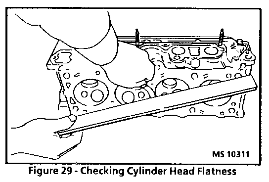
4. Cylinder head deck, intake and exhaust manifold mating surfaces for flatness. These surfaces may be reconditioned by milling. If the surfaces are "out of flat" by more than . 127 mm (. 005 inch), the surface should be milled. If more than .25 mm (.010 inch) of metal must be removed from the head, it should be replaced. 5. All threaded holes for damage. Threads may be reconditioned with thread inserts, refer to "Thread Repair" in this section. 6. Water jacket plugs seating surfaces. 7. Valve seats for excessive wear and burned spots.
o If a burnt valve condition exists, it may be necessary to recondition the valve seat insert. At no time should there be less than 4 mm of valve seat material remaining after reconditioning.
When reconditioning a valve seat, it is necessary to remove a non-adjustable rocker arm stud and install an adjustable rocker arm stud.
o Valve seats may be reconditioned by grinding. Follow the grinder manufacturer's instructions. Refer to "Engine Specifications" in this section for seat angles. If, after grinding, the new seat is too wide, it may be narrowed by using a 70" stone. The 70" stone will raise the seat. If the seats are reconditioned or replaced, refer to "Valves and Springs" in this section.
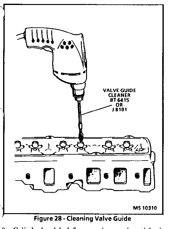
o Since the valve guide serves to support and center the valve grinder, it is essential that the valve guide is cleaned properly. If the valve guide requires reaming refer to "Valves and Springs" in this section. This must be done first.
[ ] Install or Connect
1. Oil gallery (if equipped) and cooling jacket plugs. Coat plugs with GM sealer p/n 1050026 (or equivalent). 2. Cylinder head, refer to "Cylinder Heads" in this section. NOTICE: To avoid damage, install spark plugs after the cylinder head has been installed on the engine. 3. Spark plugs.
VALVES AND SPRINGS (WITH HEAD REMOVED)
[ ] Disassemble o Rocker arms, refer to "Rocker Arms" in this section.
[!] Important o Be sure that the valve train components are kept together and identified so that they can be installed in their original location and with their same mating surface.
NOTICE: Avoid breaking the valve guide.
If the valves move the engines is in #4 firing position and should be rotated one revolution to reach the #1 position.
b. With the engine in the #1 firing position following valves may be adjusted: Exhaust - 1, 2, 3 Intake - 1, 5, 6
c. Back out adjusting nut until lash is felt at the pushrod, then turn in adjusting nut until all lash is removed. (This can be determined by rotating pus while turning adjusting nut.) When lash has been removed, turn adjusting nut in 1-1/2 additional turns (to center lifter plunger).
Crank the engine one revolution. This is th #4 firing position. With the engine in this position, the following valves may be adjusted:
Exhaust - 4, 5, 6 Intake - 2, 3, 4
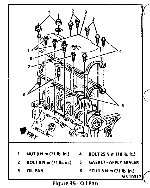
OIL PAN Figure 35 ---------- Tools Required: J 28467-A Engine Support Fixture J 36462 Engine Support Adapter Leg [ ] Remove or Disconnect
1. IAT sensor electrical connector. 2. Intake duct at throttle body. 3. Air cleaner. 4. Negative battery cable. 5. Serpentine belt, refer to "Serpentine Drive Belt" in this section. 6. Belt tensioner, refer to "Drive Belt Tensioner" in this section. 7. Support engine using J 28467-A and J 36462. 8. Raise vehicle and suitably support. Refer to GENERAL INFORMATION (SECTION 0A). 9. Drain engine oil. 10. Right tire and wheel assembly, refer to TIRE AND WHEELS (SECTION 3E). 11. Right splash shield.
CAUTION:
Failure to discon intermediate shaft from rack and pinion stub shaft can result in damage to steering gear and/or intermediate shaft. This damage can cause loss of steering control which could result in personal injury.
12. Steering gear pinch bolt, refer to POWER STEERING GEAR AND PUMP (SECTION 3B1). 13. Transaxle mount retaining nuts, refer to "Transaxle Mount" in this section. 14. Engine to frame mount retaining nuts, refer to "Engine Mount" in this section. 15. Front engine mount bracket from block. 16. Outboard flywheel/starter plastic shield. 17. Inboard flywheel metal shield. 18. Starter and hang from body, refer to CRANKING SYSTEM (SECTION 6D2). o Place jackstand under frame front center crossmember. 19. Loosen rear frame bolts - DO NOT REMOVE. 20. Front frame bolts and lower front of frame, refer to FRAME AND BODY MOUNTS (SECTION 2A). 21. DIS sensor wire. 22. Oil pan retaining bolts. 23. Oil pan retaining nuts.
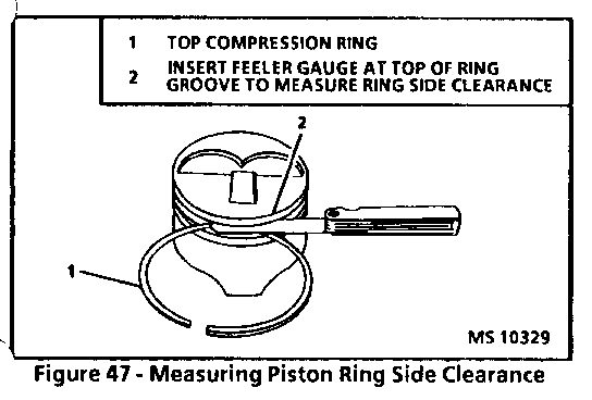
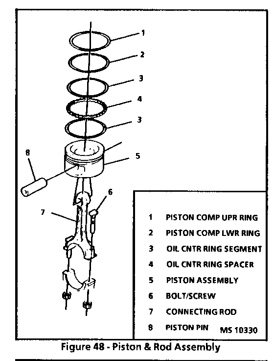
o Piston ring side clearance (compression rings). Roll the piston ring around the groove in which it is to be installed and measured the side clearance (Figure 47). If the ring is too thick, try another ring. Refer to "Engine Specifications" in this section for specification.
[ ] Assemble o Connecting rod and piston assembly.
[!] Important o Make sure that the arrow on top of the piston faces towards the front of the engine (Figure 52).
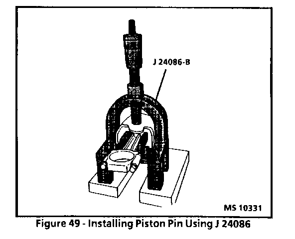
1. Place piston and connecting rod into J 24086-B or BT 7612-B/8725 (Figure 48, 49 and 50). 2. Adjust plunger of the fixture. 3. Coat the piston pin with clean engine oil. 4. Press the pinion pin into place.
[ ] Inspect 1. Piston for freedom of movement. 2. Oil control ring assembly. o Expander. o Lower oil control ring. o Upper oil control ring.
NOTICE: Use a piston ring expander to install the rings. Avoid expanding the rings more than necessary, which may cause ring damage.
3. Upper and lower compression ring. Manufacturer's mark facing up.
[!] Important o In order to provide an effective compression seal, the ring gaps must staggered (Figure 51).
[ ] Install or Connect
1. Lubricate cylinder wall and piston rings with clean engine oil. 2. Turn crankshaft to bottom dead center. 3. Connecting rod stud thread protector, if required (Figure 43). 4. Piston ring compressor (Figure 52).
[ ] Inspect
1. Bearing surfaces for: o Wear. o Gouges. o Embedded foreign material. If foreign material is found, determine its nature and source. Inspect oil pan sludge and residue. o Uneven side-to-side wear. If uneven wear is found, check for a bent crankshaft or tapered bearing journals.
2. Outer surfaces for: o Wear. Surface wear indicates either movement of the insert or high sports in the surrounding material (sport wear). o Overheating (discoloration). o Looseness or rotation (flattened tangs and wear grooves).
3. Thrust surfaces (main thrust bearing) for: o Wear. o Grooving. Grooves are caused by irregularities of the crankshaft thrust surface. Refer to "Crankshaft" in this section.
[ ] Important o Bearing failure, other than normal wear, must be investigated carefully. Inspect the crankshaft or connecting rod and the bearing bores.
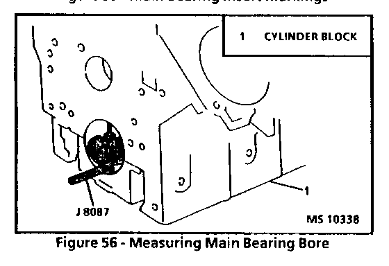
4. Connecting rods or main bearing bores as follows: o Tighten the bearing cap to specifications. o Measure the bore for taper and out of round (Figure 56). o No taper or out of round should exist.
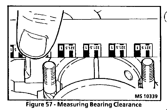
[ ] Measure o Bearing clearance. To determine the correct replacement insert size, the bearing clearance must be measured accurately. Either of the following two methods may be used, however, method "A" gives more reliable results and is preferred.
[!] Important o Method "A" yields measurement from which the bearing clearance can be computed. Method "B" yields the bearing clearance directly. Method "B" does not give any indication of bearing run-out. o Do not mix inserts of different nominal size in the same bearing bore. o Method "A".
4. Lubricate the bearing surface with clean engine oil.
NOTICE: Avoid damage to the crankshaft journal. Use connecting rod stud protectors or guide pins.
5. Crankshaft or connecting rod.
NOTICE: In order to prevent the possibility of cylinder block and/or main bearing cap damage, the main bearing caps are to be tapped into their cylinder block and/or main bearing cap damage, the main bearing caps are to be tapped into their cylinder block cavity using a brass or leather mellet before attaching bolts are installed. Do not use attaching bolts to pull main bearing caps into their seats. Failure to observe this information may damage a cylinder block or bearing cap. 6. Bearing cap. Top gently into place with a suitable tool. 7. With crankshaft bearing and bearing caps installed and both bolts started, thrust crankshaft rearward to set and align bearing caps, then thrust crankshaft forward to align rear face of thrust main bearing (Figure 58). Tighten bolts to specification.
[ ] Inspect o Pry the connecting rods back and forth and check for binding. If necessary loosen and tighten the bearing cap.
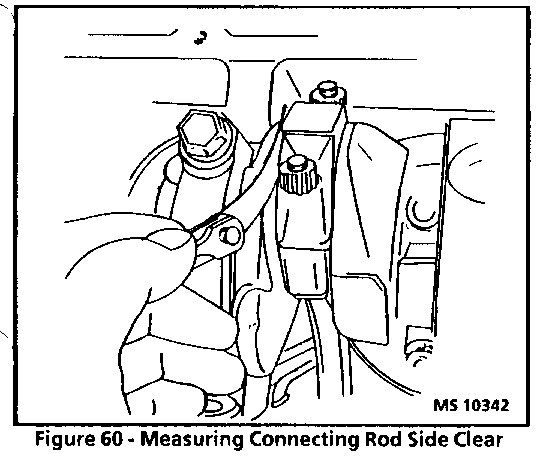
[ ] Measure o Crankshaft end play (Figure 59). o Connecting rod side clearance (Figure 60).
[ ] Clean o Oil pump intake screen. o Oil pan. 8. Oil pan, refer to "Oil Pan" in this section. 9. Engine oil filter.
10. Fill crankcase with clean engine oil. Refer to MAINTENANCE AND LUBRICATION (SECTION 0B).
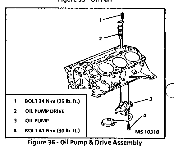
[ ] Inspect 1. Remove oil pressure sending unit and install an oil pressure gage. 2. Prime engine oil galleries: o Remove engine oil pump drive unit and rotate oil pump using drill motor and appropriate socket and extension.
NOTICE: If the oil pressure does not build up almost immediately, remove the oil pan and check oil pump suction pipe attachment to the pump. Running the engine without measurable oil pressure will cause extensive damage.
3. Start engine and observe oil pressure. 4. Check for bearing knock. If necessary, disassemble and check for adequate oil supply and proper clearances.
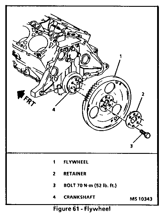
FLYWHEEL Figure 61 --------------------- [ ] Remove or Disconnect 1. Transaxle, refer to AUTOMATIC TRANSAXLE GENERAL INFORMATION AND ON-VEHICLE SERVICE (SECTION 7A). 2. Flywheel attaching bolts. o Use a suitable tool to prevent crankshaft rotation. 3. Flywheel and retainer.
[ ] Clean o Flywheel bolt threads and bolt holes.
[ ] Install or Connect
1. Apply GM Thread Locker p/n 12345382 (or equivalent) to all flywheel bolts. 2. Flywheel and bolts. 3. Bolts to flywheel. o Use a suitable tool to prevent crankshaft rotation. 4. Transaxle, refer to AUTOMATIC TRANSAXLE GENERAL INFORMATION AND ON-VEHICLE SERVICE (SECTION 7A).
FLYWHEEL BALANCE
Flywheel and torque converter imbalance can be corrected using the following procedure.
[ ] Inspect o For missing or loose converter-to-flywheel bolts. Tighten or replace as necessary. o Converter for damage or missing balance weights. If the converter is damaged or balance weights are missing, replace the converter. o Adjust
1. Change position of converter-to-flywheel 120 degrees at a time to cancel out engine and converter imbalance. Check in each position for vibration improvements. 2. If the unbalanced condition still exists, leave the converter- to-flywheel in the best balanced position. Install longer flywheel-to-converter bolts adding and removing washers until the best balance is achieved.
[!] Important o Be sure the bolts are not bottoming in the holes. If bolts bottom, cover could be dented causing internal clutch facing damage. Always rotate the converter by hand after adding washers to check for clearance.
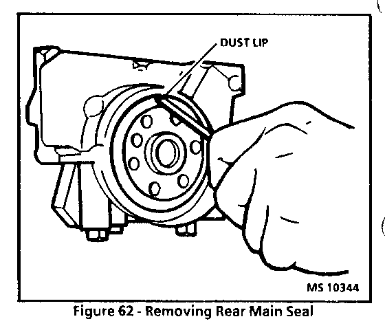
REAR MAIN SEAL Figures 62 through 64 ---------------------- Tools Required: J 28467-A Engine Support Fixture J 34686 Rear Main Bearing Oil Seal Installer J 36462 Engine Support Adapter Leg J 28467-90 Engine Support Fixture Adapters
[ ] Remove or Disconnect o Support engine with J 28467-A and J 36462.
1. Transaxle, refer to AUTOMATIC TRANSAXLE GENERAL INFORMATION AND ON-VEHICLE SERVICE (SECTION 7A). 2. Flywheel, refer to "Flywheel" in this section. 3. Confirm rear main seal leak. o Insert a screwdriver or similar tool in through the dust lip at an angle as shown in Figure 63. Pry seal out by moving the handle of the tool towards the end of the crankshaft pilot. Repeat as required around the seal until seal is removed.
[!] Important o Care must be taken not to damage crankshaft O.D. surface or chamfer with pry tool.
[ ] Inspect o Check I.D. of bore for nicks or burrs and correct as required. Inspect crankshaft for burrs or nicks on surface which contacts seal. Repair or replace crankshaft as required.
[ ] Install or Connect
1. Apply engine oil to I.D. and O.D. of new seal. Slide new seal over mandrel until back of seal bottoms squarely against collar of tool (Figures 63 and 64).
32. A/C compressor leaving rear bracket attached to compressor and hang from body, refer to AIR CONDITIONING (SECTION 1B). 33. Front exhaust pipe from crossover, refer to EXHAUST SYSTEM (SECTION 6F).
CAUTION:
Failure to disconnect intermediate shaft from rack and pinion stub shaft can result in damage to steering gear and/or intermediate shaft. This damage can cause loss of steering control which could result in personal injury.
34. Steering gear pinch bolt, refer to POWER STEERING GEAR AND PUMP (SECTION 3B1). 35. Brake hose bracket strut. 36. Brake calipers, refer to DISC BRAKE CALIPER ASSEMBLY (SECTION 5B5). 37. Lower vehicle enough to place engine/transaxle table under frame. 38. Frame bolts, refer to FRAME AND BODY MOUNTS (SECTION 2A). 39. Lower table with powertrain. 40. Raise vehicle. Refer to GENERAL INFORMATION (SECTION 0A).
[ ] Install or Connect 1. Slowly lower the body onto the powertrain. 2. Bolt struts to shock towers. 3. Frame bolts, refer to FRAME AND BODY MOUNTS (SECTION 2A). 4. Remove engine/transaxle table from under frame. 5. Brake calipers, refer to DISC BRAKE CALIPER ASSEMBLY (SECTION 5B5). 6. Brake hose bracket at strut.
CAUTION:
When installing the intermediate shaft make sure the shaft is seated prior to pinch bolt installation. If the pinch bolt is inserted into the coupling before shaft installation, the two mating shafts may disengage.
7. Steering gear pinch bolt, refer to POWER STEERING GEAR AND PUMP (SECTION 3B1). 8. Front exhaust pipe crossover. 9. A/C compressor, refer to AIR CONDITIONING (SECTION 1B). 10. Oil filter. 11. Right side splash shield. 12. Tire and wheel assemblies, refer to TIRES AND WHEELS (SECTION 3E). 13. Lower bolt securing wiring harness bracket to body side rail. 14. Lower vehicle. 15. Vacuum hose to vacuum reservoir. 16. ECM and fuse block. 17. Remaining bolts securing wiring harness bracket to body. 18. Electrical block connector to right side cowl. 19. Torque struts at engine. 20. Canister purge vacuum line. 21. Vacuum check valve at power brake booster. 22. A/C pressure switch electrical connector. 23. Accelerator and cruise control cable (If equipped) to throttle linkage. 24. Shift cable and linkage to mounting bracket. 25. Serpentine belt, refer to "Serpentine Drive Belt" in this section. 26. Fuel lines, refer to DRIVEABILITY AND EMISSIONS (SECTION 6E3-C2). 27. Heater inlet hose to rear of engine. 28. Heater outlet hose to water pump. 29. Lower radiator hose to engine. 30. Upper radiator hose to engine. 31. Transaxle fluid level indicator, refer to AUTOMATIC TRANSAXLE GENERAL INFORMATION AND ON-VEHICLE SERVICE (SECTION 7A). 32. Transaxle cooler lines from radiator, refer to AUTOMATIC TRANSAXLE GENERAL INFORMATION AND ON-VEHICLE SERVICE (SECTION 7A). 33. Cooling fan electrical connections, refer to COOLING AND RADIATOR (SECTION 6B). 34. Battery remote jump-start terminal to body. 35. Negative battery cable.
[ ] Tighten o Bolt to 15 N.m (11 lb.ft.).
36. Air cleaner assembly. 37. Intake duct to throttle body. 38. MAT sensor electrical. 39. Engine coolant. Refer to COOLING AND RADIATOR (SECTION 6B). 40. Fill crankease with clean engine oil. Refer to MAINTENANCE AND LUBRICATION (SECTION 0B). 41. Idle Learn Procedure in DRIVEABILITY AND EMISSIONS (SECTION 6E3-C2).
[ ] Inspect o Proper fluid levels. o For leaks. o Completion of repair.
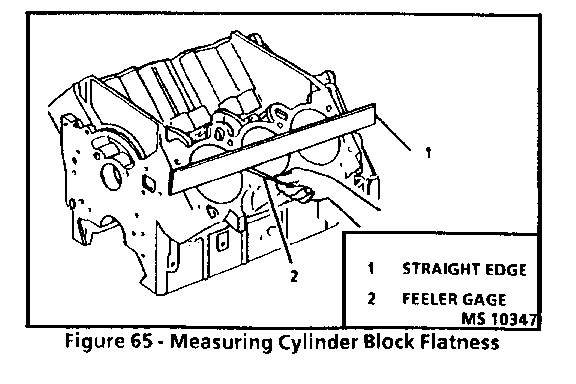
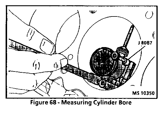
CYLINDER BLOCK Figure 65 through 69 --------------------- Tool Required: J 8087 Cylinder Bore Checking Gaged
[ ] Disassemble o Cooling jacket plugs. - Obtain a suitable self-threading screw. - Drill a hole into the plug. - Install the self-threading screw. - Pry out plug. o Oil gallery screw plugs. o Camshaft bearings, refer to "Camshaft Bearings" in this section.
[!] Important o Caustic cleaning solution destroys the bearing material. All bearings must be replaced after cleaning with a caustic solution. Do not clean bearing material or aluminum parts with caustic solutions.
[ ] Clean
o Cooling jacket plugs. - Obtain a suitable self-threading screw. - Drill a hole into the plug. - Install the self-threading screw. - Pry out plug.
o Oil gallery screw plugs. o Camshaft bearings, refer to "Camshaft Bearings" in this section.
[!] Important o Caustic cleaning solution destroys the bearing material. All bearings must be replaced after cleaning with a caustic solution. Do not clean bearing material or aluminum parts with caustic solution.
[ ] Clean o Sealing material from mating surfaces. o Boil in caustic solution. o Flush with clean water or steam. o Oil passages. o All bind holes. o Spray or wipe cylinder bores and machined surfaces with engine oil.
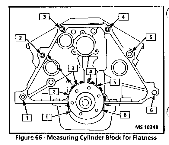
[ ] Inspect o Check surface for flatness. Use a straight edge an a feeler gage (Figure 65). Minor irregularities may be carefully machined. If more than .25 mm (.010 inch) must must be removed, replace the block. o Oil pan rail and timing cover attaching area for nicks. Minor irregularities may be cleaned up with a flat mill file. o Head bolt tapped holes. o Transaxle case mating surfaces.
NOTICE: If this surface is not flat, a broken flywheel may result.
o Temporarily install the crankshaft. Measure crankshaft flange run-out. Refer to "Crankshaft" in this section.
[ ] Measure o Six mounting hole bosses (Figure 65).
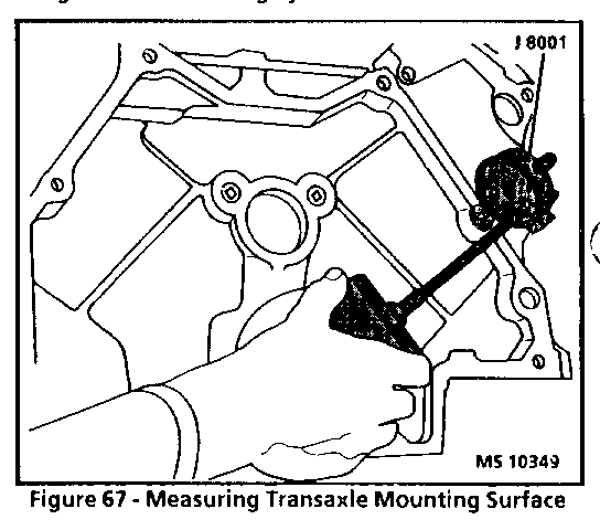
1. Hold gage plate flat against the crankshaft flange (Figure 65). 2. Place dial indicator stem on the transaxle mounting bolt hole boss (Figure 67) and set indicator to 0. 3. Take and record the readings obtained on the remaining transaxle mounting bolt hole bosses (Items 2-6, Figure 65). Measurements should not vary more than.25 mm (.010 inch). 4. If the readings vary more than .25 mm (.010 inch), recheck crankshaft flange run-out. If the run-out is excessive, replace the crankshaft.
[ ] Inspect o Threaded holes. If necessary, clean with a tap or drill out and install thread inserts. Refer to "Thread Repair" in this section.
[!] Important o The following inspections as well as reconditioning, if necessary, must be carried out with the main bearing caps installed and tightened to specification. o Make sure main bearing caps are installed correctly, with the arrows pointing toward the front of the engine. o Bearing bores, using J 8087, measure concentricity and alignment. - Camshaft. - Crankshaft. - If outside specification, replace block. - If an examination of the outside of the bearing inserts indicates minor high sports, they may be carefully removed.
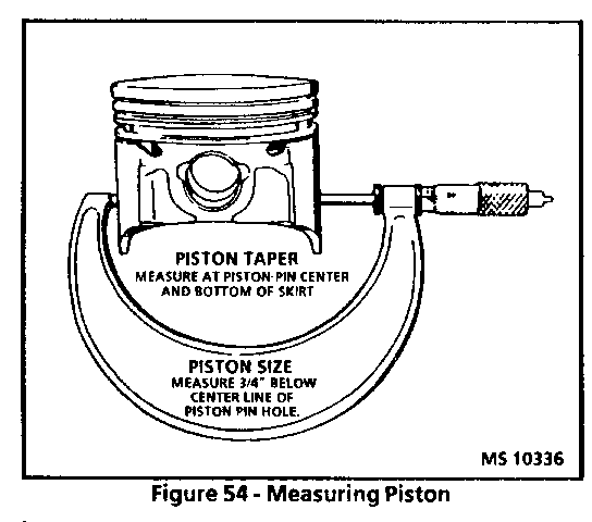
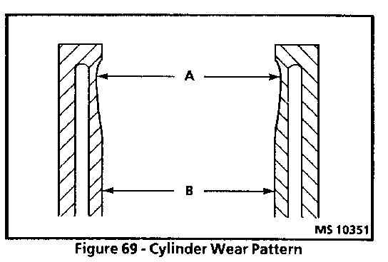
o Cylinder bore, with J 8087 measure for wear, taper, run-out and ridging (Figures 68 and 69). o If the bore is worn beyond limits, it may be rebored, honed and fitted with oversize pistons. The smallest available oversize should be selected, refer to "Piston Fitting" in this section.
[!] Important o Leave sufficient material to allow finish honing in conjunction with fitting the piston. o If the bore is glazed but otherwise serviceable, break the glaze lightly with a hone and replace the piston rings. o Make sure the honing stones are clean, sharp and straight. Move the hone slowly up and down to produce a cross-hatch pattern. Clean bore thoroughly with soap and water. Dry and rub in clean engine oil; then measure.
[ ] Assemble o Cooling jacket plugs. Apply GM sealer p/n 1050026 (or equivalent). o Oil gallery screw plug.
[!] Important o Make sure plugs with oil holes are installed in their original position to provide lubrication to the timing chain and to the distributor. o Camshaft bearings. Refer to "Camshaft Bearings" in this section.
CAMSHAFT
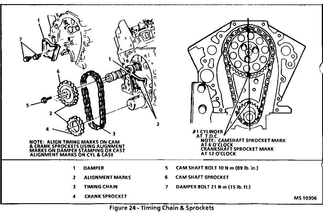
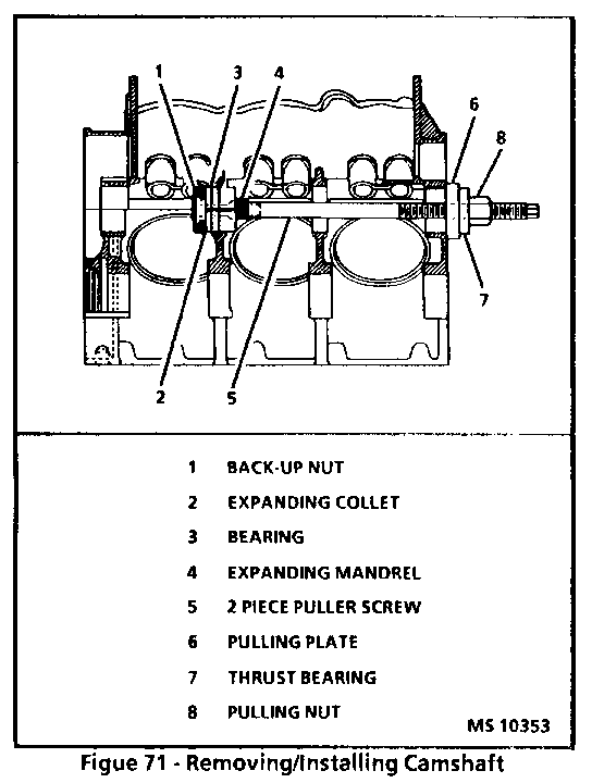
[ ] Remove or Disconnect 1. Engine refer to "Engine Assembly" in this section. 2. Valve lifters, refer to "Valve Lifters" in this section. 3. Crankcase front cover, refer to "Front Cover" in this section. 4. Timing chain and sprocket, refer to "Timing Chain and Sprocket" in this section. NOTICE: All camshaft journals are the same diameter and care must be exercised in removing camshaft to avoid damage to bearings. o Place bearing onto J 33049 and index the oil hole(s) of the bearing with the oil passage(s) in the cylinder block. Pull bearing into place.
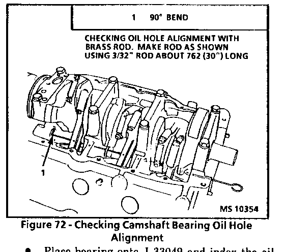
NOTICE: Proper alignment of the oil holes is critical. Restriction of the oil flow will cause severe engine damage.
2. Camshaft plug. o Apply GM RTV sealer p/n 1052914 (or equivalent) to the plug before installing.
[ ] Inspect o With a piece of 3/32 inch brass rod with a 90 deg. bend at the end, probe the bearing oil holes and verify that they are properly aligned (Figure 72).
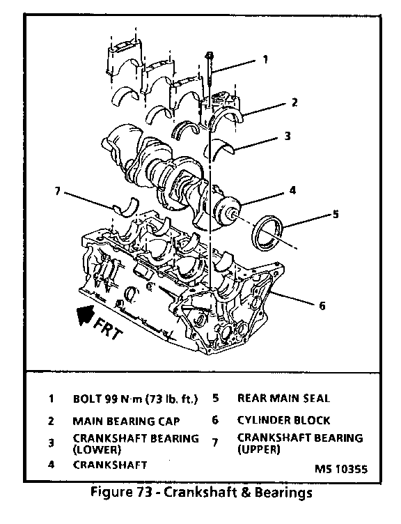
CRANKSHAFT (ENGINE ON STAND) Figure 73 ---------------------------- [ ] Remove or Disconnect o Drain engine oil.
1. Oil pan, refer to "Oil Pan" in this section. 2. Torsional damper, refer to "Torsional Damper" in this section. 3. Front cover, refer to "Front Cover" in this section. 4. Timing chain and sprocket, refer to "Timing Chain and Sprocket" in this section. 5. Timing chain tensioner. 6. Flywheel, refer to "Flywheel" in this section. 7. Oil pump, refer to "Oil Pump" in this section. 8. Spark plug. 9. Mark connecting rod and main caps so that they can be installed in the same location. 10. Rod caps and install thread protectors in connecting rods. o Push pistons to top of cylinders. 11. Main bearing caps.
SPECIFICATIONS ==============
FASTENER TORQUE SPECIFICATION
Camshaft Sprocket Bolt .................................28 N-m (21 lb.ft.) Connecting Rod Nut......................................53 N-m (39 lb.ft.) Cylinder Head Bolt......................................Figure 27 Drive Belt Tensioner Bolt...............................50 N-m (37 lb.ft.) Engine Bracket to Engine Bolt ..........................See Figure 12 Engine Bracket to Engine Mount Nut......................45 N-m (34 lb.ft.) Engine Mount to Frame Nut...............................45 N-m (34 lb.ft.) Engine Strut Bracket to Engine Bolt.....................See Figure 12 Engine Strut to Tie Bar Bracket ........................56 N-m (41 lb.ft.) Engine Strut to Upper Tie Bar...........................23 N-m (17 lb.ft.) Exhaust Crossover Nut ..................................25 N-m (18 lb.ft.) Exhaust Manifold Heat Shield Nut........................10 N-m (89 lb.in.) Exhaust Manifold to Cylinder Head Bolt..................25 N-m (18 lb.ft.) Flywheel Bolt ..........................................70 N-m (52 lb.ft.) Front Cover Bolt........................................Figure 23 Intake Manifold Bolt....................................Figure 15 Oil Filter .............................................15 N-m (11 lb.ft.) Oil Level Indicator Retaining Nut.......................25 N-m (18 lb.ft.) Oil Pan Bolt.............................................8 N-m (71 lb.in.) Oil Pan Nut ........................................... .8 N-m (71 lb.in.) Oil Pan Rear Bolts (2)..................................25 N-m (18 lb.ft.) Oil Pan Stud to Cylinder Block...........................8 N-m (71 lb.in.) Oil Pump Drive Bolt....................................34 N-m (25 lb.ft.) Oil Pump Mounting Bolt..................................41 N-m (30 lb.ft.) Rocker Arm Cover Bolt...................................10 N-m (89 lb.in.) Rocker Arm Nut ........................................ 25 N-m (18 lb.ft.) Timing Chain Dampener Bolt .............................21 N-m (15 lb.ft.) Torsional Dampener..................................... 103 N-m (76 lb. ft.)
SYSTEM CHECK
o For a guide outlining the Instrument Cluster operation, refer to the Lumina Service Manual, Section 8A-80.
SYSTEM DIAGNOSIS
o Do the tests listed for your symptom in the Symptom Table below.
SYMPTOM TABLE =============
SYMPTOM FOR DIAGNOSIS ----------------------------- ------------------------------------ Fuel Gage reads full at Check Fuel Sender In-line fuse all times with Ignition for an open. If fuse is Switch in RUN OK, do Test A
Fuel level indicated Do Test A by gage is incorrect
All other symptoms indicated Refer to System Diagnosis in the by gage except fuel level Lumina Service Manual, Section and % Methanol are 8A-80 incorrect
% Methanol Gage displays "--" Check/repair ORN (461) wire for short and the 'Service Engine Soon' to ground indicator flashes with Ignition Switch in RUN
% Methanol Gage displays "--" Check/repair ORN (461) wire for open and the "Service Engine Soon' or short to battery indicator does not flash with Ignition Switch in RUN
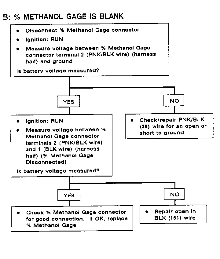
% Methanol Gage display is Do Test B blank
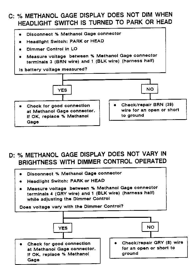
% Methanol Gage display does Do Test C not dim with Park or Headlights turned on
% Methanol Gage display Do Test D does not vary in brightness with Dimmer Control operated
General Motors bulletins are intended for use by professional technicians, not a "do-it-yourselfer". They are written to inform those technicians of conditions that may occur on some vehicles, or to provide information that could assist in the proper service of a vehicle. Properly trained technicians have the equipment, tools, safety instructions and know-how to do a job properly and safely. If a condition is described, do not assume that the bulletin applies to your vehicle, or that your vehicle will have that condition. See a General Motors dealer servicing your brand of General Motors vehicle for information on whether your vehicle may benefit from the information.
