INTERFERENCE, HEATER HOSE AND COOLANT RESERVOIR HOSE CLIP

SUBJECT: INTERFERENCE, LEAK AND/OR NOISE WITH COOLANT RESERVOIR TO HEATER HOSE OR A/C COMPRESSOR (REPAIR PROCEDURE)
VEHICLES AFFECTED: 1991 W-CAR
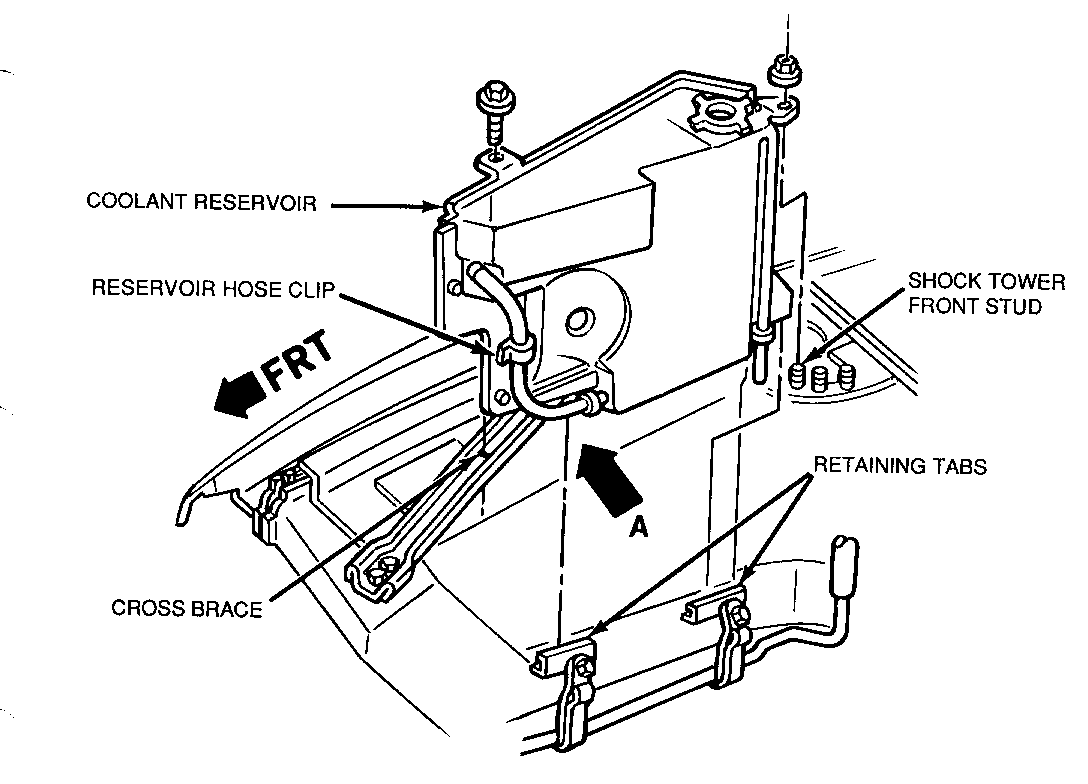
Condition: #1. On both the 3.1L (LHO) and 3.4L (LQ1) engines. Interference between the heater outlet hose and the clip on the coolant reservoir hose.
#2. Only on the 3.4L (LQ1) engine. Coolant reservoir hose cut by the A/C compressor pulley.
Cause: #1. The reservoir hose clip is located too low and rubs on the heater outlet hose.
#2. The coolant reservoir is not installed in one or both of the lower retaining tabs, causing interference of the reservoir hose and the A/C compressor pulley. This may also be the source of a noise condition.
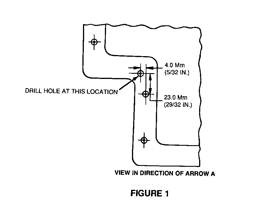
Correction: #1. Move the reservoir hose clip higher and forward by drilling a new mounting hole in the reservoir.
#2. Install the reservoir in the two lower retaining tabs and check the clearance between the hose and the A/C compressor pulley.
PROCEDURE FOR CORRECTION #1: ---------------------------- 1. Remove the coolant reservoir.
2. Measure for location and drill a 6.3 mm (1/4") diameter hole above and forward of the present location of the hose clip using the dimensions, shown in View A of Figure 1.
3. Move the hose clip to the new location and install the coolant reservoir.
NOTICE: BEFORE INSTALLING THE RESERVOIR ON 3.4L (LQ1) ENGINE CHECK THE RESERVOIR HOSE FOR DAMAGE. IF HOSE IS DAMAGED, REPLACE THE HOSE.
4. To verify that the reservoir is properly installed in the two lower retaining tabs on the 3.41 (LQ1) engine continue on with the following steps for Correction #2.
INFORMATION AND PROCEDURE FOR CORRECTION #2 ------------------------------------------- When the reservoir is properly mounted in the two lower retaining tabs there should be a clearance of 14 mm (9/16") between the reservoir hose, at the bottom of the reservoir, and the A/C compressor pulley. This is very difficult to see and verify from the top underhood position. For that reason, the following steps should be taken.
1. Raise the vehicle. 2. At the RH front wheel well, remove enough of the plastic retainers (push pins) in the inner splash shield to allow hand clearance into the engine compartment. 3. With your hand, feel for the reservoir being in the two lower retaining tabs, as shown in Figure 1. 4. Use your finger to estimate the clearance between the hose and the compressor pulley of 14 mm (9/16"). If, in your judgment, the clearance is not adequate, try to tighten the hose routing between clips and/or use plastic tie (chicken band) to obtain the necessary clearance. 5. Install splash shield retainers. 6. Lower the vehicle.
Use the most applicable Labour Operation and Time from the Canadian Labour Time Guide.


General Motors bulletins are intended for use by professional technicians, not a "do-it-yourselfer". They are written to inform those technicians of conditions that may occur on some vehicles, or to provide information that could assist in the proper service of a vehicle. Properly trained technicians have the equipment, tools, safety instructions and know-how to do a job properly and safely. If a condition is described, do not assume that the bulletin applies to your vehicle, or that your vehicle will have that condition. See a General Motors dealer servicing your brand of General Motors vehicle for information on whether your vehicle may benefit from the information.
