CLUTCH BUMP WITH 3.4L AND M/T ADD SWITCH AND REPLACE MEMCAL

TRANSMISSION APPLICATIONS: 3.4L (VIN CODE X) AND MANUAL TRANSMISSION
SUBJECT: CLUTCH "BUMP" (ADD SWITCH AND REPLACE MEMCAL)
VEHICLE APPLICATIONS: 1991 "W" CAR
Condition:
---------- The customer may comment that the manual transmission has a "bump" sensation when decelerating. The engine may decelerate too quickly if the driver lets up on the accelerator before depressing the clutch, causing a momentary "bump" sensation just before the clutch is fully released.
Cause:
------ There is no "clutch anticipate" signal to the ECM to allow for less abrupt fuel cutoff to the injectors during shifting.
Correction:
-----------
PARTS LIST
Part No. Name -------- ----
12126540 Kit, Clutch Anticipate, contains:
(1) 4-way connector with wires
(1) Wire with terminals on both ends
(3) Crimp connectors
16166146 MEM-CAL
10180569 Switch, C/C Release and Clutch Anticipate
Parts needed if vehicle does not have cruise control:
10075405* Retaining clip
10094202* Actuator Tab
11503747* Nut
10042901* Bolt
* Parts are currently available from CANSPO.
1. Disconnect negative battery cable.
2. Remove the left hand IP sound insulator panel.
3. Add a "clutch anticipate" switch as follows:
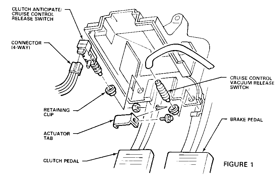
a. If the vehicle has cruise control, remove the existing clutch switch and discard it. Remove the clip and reinstall it in the opposite direction. Cut the connector from the two cruise control switch wires (brown and brown/white wires), as close to the connector body as possible, and discard the connector.
b. Install a new switch, P/N 10180569, in the existing clip. If the vehicle does not have cruise control, add a clip, P/N 10075405, as shown in Figure 1. Add an actuator tab, P/N 10094202, to the clutch pedal, and secure with a nut, P/N 11503747, and bolt, P/N 10042901. Torque to 10 Nm (7 ft. lb.).
c. Obtain the four-way clutch anticipate switch connector/jumper from the kit, P/N 12126540. Using the repair procedures for crimp and seal splice sleeves shown in Section 8A of the Service Manual, connect the wires as follows:
Cavity A - Splice the brown/white wire to the brown/white wire from the old clutch release switch connector (this wire not used if vehicle does not have cruise).
Cavity B - Splice the brown wire to the brown wire from the old clutch release switch connector (this wire not used if vehicle does not have cruise).
Cavity C - Black ground wire. Attach the ring terminal to a convenient chassis ground, such as the turn signal flasher bracket screw.
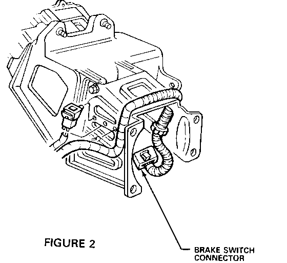
Cavity D - The purple wire will connect to the purple wire from cavity B (TCC circuit) of the brake switch connector (See Figure 2). This wire, which goes to the bulkhead connector, is not used with manual transmissions. Remove the brake switch connector, and cut the purple wire from cavity B. The old terminal can stay in the connector. Reinstall the brake switch connector. Splice the two purple wires together.
4. Connect the four-way connector to the switch, and adjust the switch as follows:
a. Push the clutch pedal in all the way.
b. Push the switch in until it bottoms against the clip.
c. Pull up on the clutch pedal until it is in it's full out position. This should properly adjust the switch. Make sure the switch does not hold the clutch pedal in.
5. From under the hood, install the single purple wire from the kit, from the bulkhead connector to the ECM as follows:
a. Remove the coolant recovery bottle.
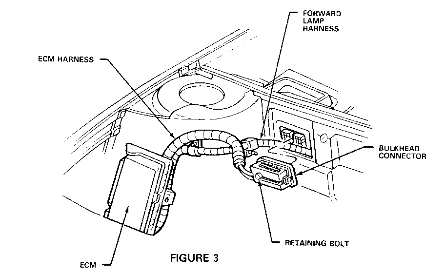
b. Remove the bulkhead connector as shown in Figure 3.
c. Remove blue Terminal Position Assurance (TPA) device from the back side of the connector. Remove the seal plug from cavity J3. Install the male terminal end of the wire into cavity J3, making sure it is locked firmly in place. Reinstall the TPA.
d. Reinstall the bulkhead connector.
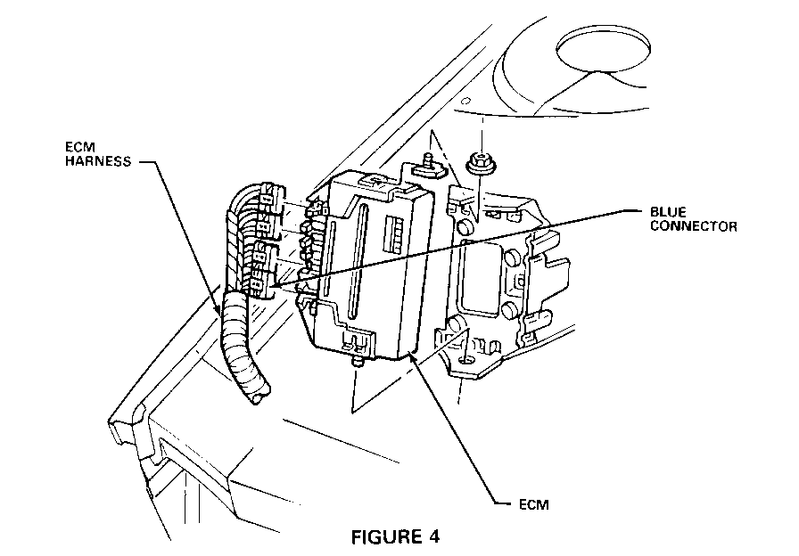
e. Remove the ECM from it's mounting bracket. Remove the blue connector from the ECM as shown in Figure 4.
f. Remove the red TPA and locate cavity D22. Remove the seal plug from cavity D22 and install the female terminal end of the wire, making sure the terminal is locked in place. Reinstall the red TPA.
9. Reinstall the ECM connector.
h. Secure the wire to the existing wire harness with electrical tape.
6. Replace the MEM-CAL with P/N 16166146. Reinstall the ECM in it's mounting bracket. Reinstall the coolant recovery bottle.
7. Reconnect the negative battery cable.
8. Replace the IP sound insulator panel.
9. Using the Tech-1 tool, perform the relearn procedure, following the instructions given by the tool.
Warranty Information: 1.2 hours


General Motors bulletins are intended for use by professional technicians, not a "do-it-yourselfer". They are written to inform those technicians of conditions that may occur on some vehicles, or to provide information that could assist in the proper service of a vehicle. Properly trained technicians have the equipment, tools, safety instructions and know-how to do a job properly and safely. If a condition is described, do not assume that the bulletin applies to your vehicle, or that your vehicle will have that condition. See a General Motors dealer servicing your brand of General Motors vehicle for information on whether your vehicle may benefit from the information.
