FUEL PUMP NOISE,HESIT., LOSS OF POWER-PUMP OR CONTAM. FUEL

Subject: FUEL PUMP NOISE, ENGINE HESITATION, SAG, LOSS OF POWER OR NO START
Model and Year: 1991-92 CAVALIER AND LUMINA
THIS BULLETIN CANCELS AND SUPERSEDES DEALER SERVICE BULLETIN NO. 92-176-6C, DATED APRIL 1992. THE 1991 MODEL YEAR HAS BEEN ADDED AS WELL AS THE LUMINA. THE DIAGNOSTICS HAVE ALSO BEEN UPDATED. ALL COPIES OF 92-176-6C SHOULD BE DISCARDED.
CONDITION:
Some vehicles may experience fuel pump noise/whine and/or low fuel pressure, sluggish performance, loss of power or hesitation or service engine soon light with codes 32 or 44. Some cars may experience the condition most evident during the first five minutes of operation or under heavy acceleration.
CAUSE:
The fuel pump may contain a tight bearing that causes internal binding in the pump.
OR (Some "J" cars only)
There may be some contamination in the fuel tank. This is caused by the die lubricant not being completely rinsed out in the manufacture of the fuel tanks. This will appear as a gel or soap on the modular fuel sender strainer. Vehicles that may exhibit this condition have the following VIN breakpoints:
N7160546 - N7184417
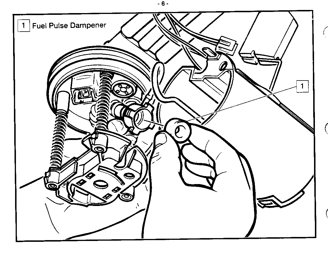
IMPORTANT: On all J, L vehicles with modular senders, ALWAYS replace the pulse dampener seal supplied in the fuel pump kit. Failure to replace the pulse dampener seal may result in repeated low fuel pressure situations. Refer to figure #4 item 1.
CORRECTION:
Follow appropriate service manual procedures when diagnosing fuel related problems. The vehicle may need to be operated under a load while monitoring fuel pressure to detect the problem. Make certain the fuel system is performing to specifications before other engine control system components are serviced. When the symptoms are present the condition may be verified by:
Diagnostic Aids:
A. A drop in fuel pressure of 69 kPa (lO psi) or more when testing fuel pressure as outlined in the Service Manual.
B. Fuel pressure drops or does not increase by at least 35 kPa (5 psi) when throttle moves from idle to part throttle.
C. Oxygen sensor reading biased toward lean when the engine is under load.
D. Condition may be intermittent, temporarily eased when accelerator pedal is reapplied.
IMPORTANT: If no other cause for fuel starvation is found, replace the fuel pump.
For electrical intermittences, see Section 8A of the appropriate Service Manual. Also, see instruction on use of required tool J38125.
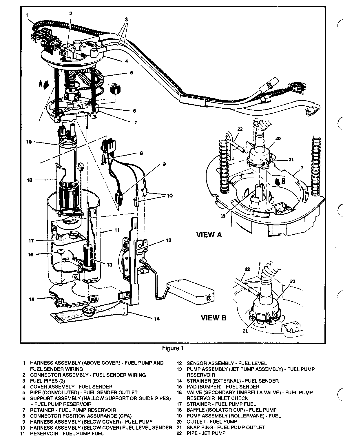
Fuel Pump Replacement Procedure: (For vehicles with modular fuel sender) refer to Figure 1 unless otherwise noted.
1. Remove modular fuel sender as outlined in the appropriate service manual, Section 6C, "Modular Fuel Sender Replacement."
NOTICE: "J" vehicles affected with contamination will have a gel appearing substance on the fuel sender external strainer. If found, flush fuel tank with warm water for 5 minutes. Remove all water and be certain all water is wiped out of fuel tank by shaking upside down and wiping thoroughly with clean, dry, lint-free shop cloths. Add a can of "Fuel Additive' P/N 1051516 to aid in complete removal of all water. If contamination was found, replace fuel filter.
2. Remove external fuel strainer.
3. Remove CPA#8 (connector position assurance) from electrical connector and disconnect fuel pump electrical connector.
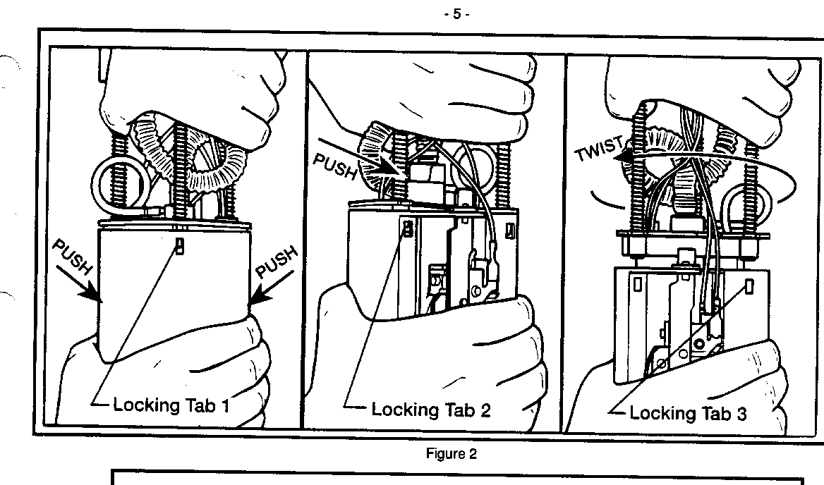
4. Gently release tabs on sides of fuel sender to cover assembly. Begin by squeezing the sides of the reservoir and releasing the tab opposite the fuel level sensor. Move clockwise to release the second and third tab in the same manner. (Figure 2)
5. Lift cover assembly out far enough to disconnect the fuel pump electrical connection.
6. Carefully pry snap ring (#21) out of groove on fuel pump outlet. (View B)
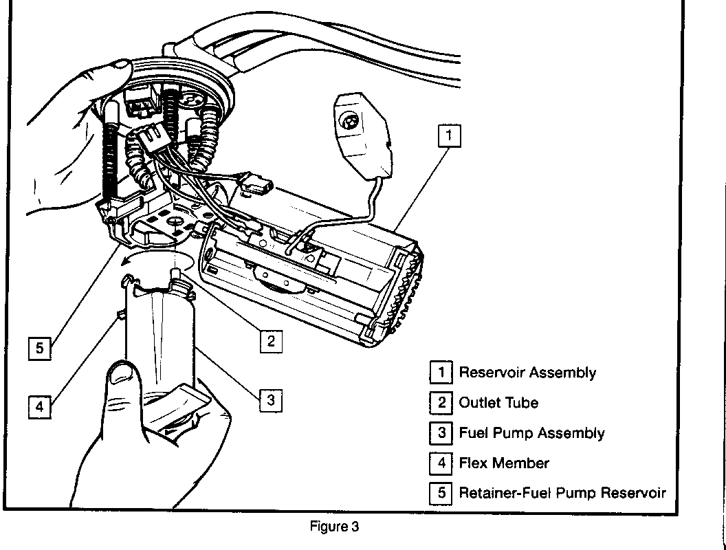
7. Rotate fuel pump baffle #18 counterclockwise and remove baffle pump assembly from retainer #7.
8. Replace the fuel pump seal/dampener. (Figure 4)
9. Install fuel pump outlet retainer #21 on fuel pump outlet #20. Index the snap ring so that the ends are positioned in the groove #22 facing the fuel pump electrical connection. (View A and B)
10. Install new fuel pump and baffle assembly onto reservoir retainer #7 and rotate clockwise until seated.
11. Place fuel pump outlet #20 over retainer #7 so that snap ring ends #21 face fuel pump electrical connection and press firmly into place making certain the snap ring is seated and over each tab on outlet. (View B)
IMPORTANT: Gently pull on fuel pump outlet to assure a secure fastening. If not secure, replace fuel sender. Failure to fully seat retainer snap ring may cause aeration and poor performance.
12. Lower retainer assembly #7 partially into reservoir. Line up all three sleeve tabs.
IMPORTANT: Gently pull on fuel pump reservoir from retainer to assure a secure fastening. If not secure, replace entire fuel sender.
13. Install fuel pump connector and CPA#8 (connector position assurance) to fuel sender cover #7.
14. Install new external fuel strainer #1 4.
15. Reinstall fuel tank in vehicle as outlined in "Modular Fuel Sender Replacement" in the appropriate Service Manual.
PARTS INFORMATION:
Fuel Filter P/N 25121293 Fuel Pump Kit P/N 25028921 Fuel Additive P/N 1051516
Parts are expected to be available on April 6, 1992. In case of limited inventory, parts will be placed on 400 control to waive VIP surcharges. Only verifiable emergency VIP orders will be accepted. SPO will make every effort to obtain parts. However, the part will be shipped premium transportation at dealer's expense and all other order types will be placed on backorder until the 400 control is removed.
WARRANTY INFORMATION:
'J" Fuel Contamination: Labor Operation Number T1848 Labor Time 1.7 Hours
'J" Pump Relacement Only: Labor Operation Number T1849 Labor Time 1.4 Hours
1 HARNESS ASSEMBLY (ABOVE COVER) - FUEL PUMP AND FUEL SENDER WIRING
2 CONNECTOR ASSEMBLY - FUEL SENDER WIRING
3 FUEL PIPES (3)
4 COVER ASSEMBLY - FUEL SENDER
5 PIPE (CONVOLUTED) - FUEL SENDER OUTLET
6 SUPPORT ASSEMBLY (THEE HOLLOW SUPPORT OR GUIDE PIPES) - FUEL PUMP RESERVOIR
7 RETAINER - FUEL PUMP RESERVOIR
8 CONNECTOR POSITION ASSURANCE (CPA)
9 HARNESS ASSEMBLY (BELOW COVER) - FUEL PUMP
10 HARNESS ASSEMBLY (BELOW COVER) FUEL LEVEL SENDER
11 RESERVOIR - FUEL PUMP FUEL
12 SENSOR ASSEMBLY - FUEL LEVEL
13 PUMP ASSEMBLY (JET PUMP ASSEMBLY) - FUEL PUMP RESERVOIR
14 STRAINER (EXTERNAL) - FUEL SENDER
15 PAD (BUMPER) - FUEL SENDER
16 VALVE (SECONDARY UMBRELLA VALVE) - FUEL PUMP RESERVOIR INLET CHECK
17 STRAINER - FUEL PUMP FUEL
18 BAFFLE (ISOLATOR CUP) - FUEL PUMP
19 PUMP ASSEMBLY (ROLLERVANE) - FUEL
20 OUTLET - FUEL PUMP
21 SNAP RING - FUEL PUMP OUTLET
22 PIPE - JET PUMP


General Motors bulletins are intended for use by professional technicians, not a "do-it-yourselfer". They are written to inform those technicians of conditions that may occur on some vehicles, or to provide information that could assist in the proper service of a vehicle. Properly trained technicians have the equipment, tools, safety instructions and know-how to do a job properly and safely. If a condition is described, do not assume that the bulletin applies to your vehicle, or that your vehicle will have that condition. See a General Motors dealer servicing your brand of General Motors vehicle for information on whether your vehicle may benefit from the information.
