Engine Mount Bracket Replacement Left Side
Removal Procedure
Tools Required
| • | J 36462 Engine
Support Adapter Leg |
| • | J 35953 Engine
Support Foot Modification |
- Remove the hood panel assembly. Refer to Body and Front End.
- Remove the air cleaner duct. Refer to Engine Controls.
- Remove the drive belt. Refer to
Drive Belt Replacement
.
- Remove the electric engine cooling fan assemblies.
- Install the J 28467-360
.
- Install the J 28467-90
.
- Install the J 36462
.
- Install the J 35953
.
- Drain the coolant.
- Disconnect the engine oil cooler hose from the 3-way connector
at the oil cooler.
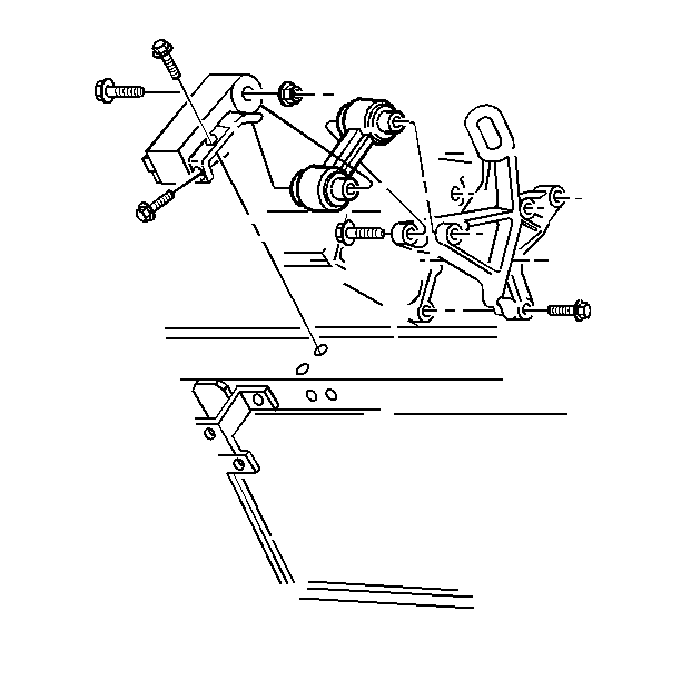
- Remove the engine mount strut bracket at the upper radiator support.
- Remove the upper radiator support.
- Remove the engine cooling fans.
- Remove the A/C compressor mounting bolts. Refer to HVAC.
- Hang the A/C compressor aside.
- Raise and suitably support the vehicle. Refer to General Information.
- Remove the right front tire and wheel assembly. Refer to Tires
and Wheels.
- Remove the right engine splash shield. Refer to Drive Axle.
- Remove the rear A/C compressor bracket. Refer to HVAC.
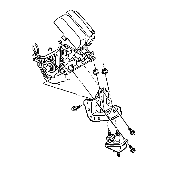
- Remove the engine mount nuts at the engine mount bracket.
- Lower the vehicle.
- Raise the engine assembly approximately one inch.
- Raise the vehicle. Suitable support the vehicle. Refer to General
Information.
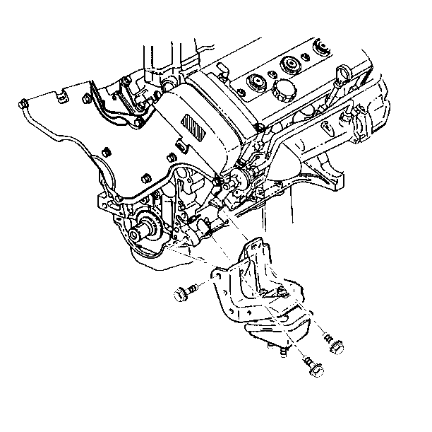
- Remove the engine mount bracket bolts at the engine block.
- Remove the wiring clips and the engine mount bracket.
Installation Procedure
Tools Required
| • | J 36462 Engine
Support Adapter Leg |
| • | J 35953 Engine
Support Foot Modification |
Notice: Reinstall the silver-finished front engine mount bracket bolt. Failure
to reinstall the bolt results in excessive loads being placed on the tow side
bracket bolts. This could cause the side bolts to separate from the engine
block.

- Install the engine mount bracket.

- Install the engine mount bracket bolts.
Tighten
| • | Tighten the front engine mount bracket bolts to 103 N·m
(76 lb ft). |
| • | Tighten the side engine mount bracket bolts to 58 N·m
(43 lb ft). |
Notice: Use the correct fastener in the correct location. Replacement fasteners
must be the correct part number for that application. Fasteners requiring
replacement or fasteners requiring the use of thread locking compound or sealant
are identified in the service procedure. Do not use paints, lubricants, or
corrosion inhibitors on fasteners or fastener joint surfaces unless specified.
These coatings affect fastener torque and joint clamping force and may damage
the fastener. Use the correct tightening sequence and specifications when
installing fasteners in order to avoid damage to parts and systems.
- Lower the vehicle.
- Lower the engine.
- Remove the J 28467-360
.
- Remove the J 28467-90
.
- Remove the J 36462
.
- Remove the J 35953
.
- Raise the vehicle. Suitable support the vehicle. Refer to General
Information.
- Install the engine mount nuts on the engine mount bracket.
Tighten
Tighten the engine mount nuts to 43 N·m (32 lb ft).
- Install the rear A/C compressor bracket. Refer to HVAC.
- Install the right engine splash shield. Refer to Drive Axle.
- Install the right front tire and wheel assembly. Refer to Tires
and Wheels.
- Lower the vehicle.
- Position the A/C compressor. Refer to HVAC.
- Install the cooling fans.
- Install the upper radiator support.
- Install the cooling fan bolts.

- Install the engine mount strut bracket.
- Connect the engine oil cooler hose to the oil cooler.
- Install the electric engine cooling fan.
- Install the drive belt. Refer to
Drive Belt Replacement
.
- Refill the coolant.
- Install the air cleaner duct. Refer to Engine Controls.
- Install the hood panel. Refer to Body Front End.
Engine Mount Bracket Replacement Right Side
Removal Procedure
Tools Required
| • | J 36462 Engine
Support Adapter Leg |
| • | J 35953 Engine
Support Foot Modification |
- Remove the hood panel. Refer to SECTION 10-5.
- Remove the electric engine cooling fan.
- Install the J 28467-360
.
- Install the J 28467-90
.
- Install the J 36462
.
- Install the J 35953
.
- Raise the vehicle. Suitably support the vehicle. Refer to SECTION
0A.
- Remove the right front tire and wheel assembly. Refer to SECTION
3E.
- Remove the generator. Refer to SECTION 6D3.
- Remove the rear generator pencil brace. Refer to SECTION 6D3.
- Remove the generator mounting bracket. Refer to SECTION 6D3.
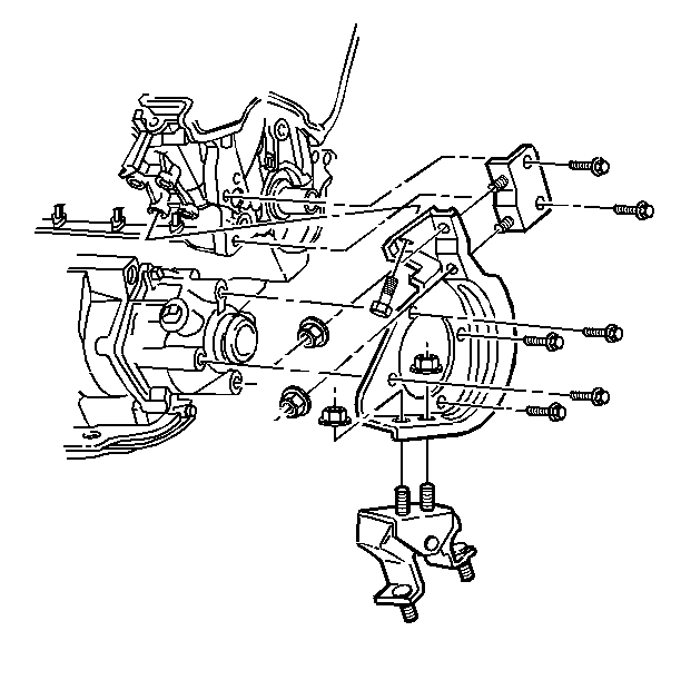
- Remove the engine mount nuts at the engine mount bracket.
- Remove the engine mount nuts at the engine mount frame.
- Lower the vehicle.
- Raise the engine.
- Raise the vehicle. Suitable support the vehicle. Refer to SECTION
0A.
- Remove the transaxle bracket retaining bolts at the transaxle.
Refer to SECTION 7A.
- Remove the engine mount bracket retaining bolts at the engine.
- Remove the engine mount and the engine mount bracket.
Installation Procedure
Tools Required
| • | J 36462 Engine
Support Adapter Leg |
| • | J 35953 Engine Support
Foot Modification |

- Install the rear engine mount.
- Install the rear engine mount bracket.
- Install the bracket to engine retaining bolts.
Tighten
- Tighten the side of the block engine retaining bolts to 58 N·m
(43 lb ft).
- Tighten the front of the block engine retaining bolts to 102 N·m
(75 lb ft)
Notice: Use the correct fastener in the correct location. Replacement fasteners
must be the correct part number for that application. Fasteners requiring
replacement or fasteners requiring the use of thread locking compound or sealant
are identified in the service procedure. Do not use paints, lubricants, or
corrosion inhibitors on fasteners or fastener joint surfaces unless specified.
These coatings affect fastener torque and joint clamping force and may damage
the fastener. Use the correct tightening sequence and specifications when
installing fasteners in order to avoid damage to parts and systems.
- Install the transaxle retaining bolts on the rear engine mount
bracket.
Tighten
Tighten the transaxle retaining bolts to 75 N·m (55 lb ft).
- Lower the vehicle.
- Remove the J 28467-360
.
- Remove the J 28467-90
.
- Remove the J 36462
.
- Remove the J 35953
.
- Lower the engine.
- Raise the vehicle. Suitable support the vehicle. Refer to SECTION
0A.
- Install the rear engine mount nuts on the rear engine mount bracket
and on the rear engine mount frame.
Tighten
| • | Tighten the rear engine mount nuts to the frame to 43 N·m
(32 lb ft). |
| • | Tighten the rear engine mount nuts to the bracket to 47 N·m
(35 lb ft). |
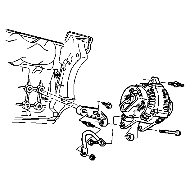
- Install the generator mounting bracket. Refer to SECTION 6D3.
- Install the generator pencil brace. Do no tighten the pencil brace.
- Install the generator. Refer to SECTION 6D3..
- Install the right front tire and wheel assembly. Refer to SECTION
3E.
- Lower the vehicle.
- Install the electric engine cooling fan.
- Install the hood panel. Refer to SECTION 10-5.


