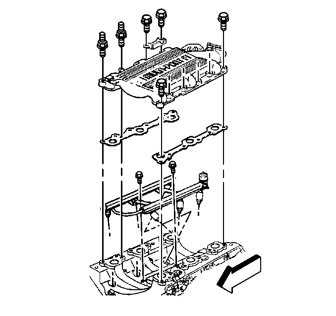
For 1990-2009 cars only
Removal Procedure
- Drain coolant. Refer to Cooling and Radiator.
- Remove the air inlet duct.
- Remove the accelerator and cruise control cable at throttle body and accelerator control cable bracket.
- Remove the fuel pipe clip at accelerator control cable bracket.
- Remove the accelerator control cable bracket.
- Remove the vacuum lines, noting position of hoses.
- Remove the electrical connectors at the IAC valve, MAF, and TP sensors.
- Remove the EGR valve.
- Remove the heater inlet pipe hose clamps at heater inlet pipe.
- Remove the ignition coil assembly front bolt.
- Loosen ignition coil assembly rear nuts.
- Remove the MAP sensor and bracket.
- Remove the alternator braces.
- Remove the upper intake manifold bolts and studs.
- Remove the upper intake manifold and gaskets.
- Remove the throttle body from upper intake manifold.
- Remove the heater hoses from upper intake manifold.
- Remove the fuel pressure regulator vacuum line.

Installation Procedure
Notice: Do not use solvent of any type when cleaning the gasket surfaces on the intake manifold and the throttle body assembly, as damage to the gasket surfaces and throttle body assembly may result.
Use care in cleaning the gasket surfaces on the intake manifold and the throttle body assembly, as sharp tools may damage the gasket surfaces.- Clean the gasket sealing surfaces.
- Install the throttle body to upper intake manifold.
- Install the heater hoses to upper intake manifold.
- Install the fuel pressure regulator vacuum line.
- Install the new upper intake manifold gaskets.
- Install the upper intake manifold.
- Guide upper intake manifold heater hoses onto heater inlet pipe.
- Install the upper intake manifold bolts and studs.
- Install the heater inlet pipe hose clamps at heater inlet pipe.
- Install the alternator braces.
- Install the MAP sensor and bracket.
- Install the ignition coil assembly front bolts.
- Tighten the ignition coil assembly rear nuts.
- Install the EGR bolts.
- Install the vacuum lines as noted during disassembly.
- Install the electrical connectors at IAC valve, MAF and TP sensors.
- Install the accelerator control cable bracket.
- Install the fuel pipe clip at accelerator control cable bracket.
- Install the accelerator and cruise control cables at throttle body and accelerator control bracket.
- Adjust the accelerator control cable. Refer to accelerator control cable adjustment portion of the section.
- Adjust the cruise control cable. Refer to cruise control cable adjustment portion of this section.
- Install the air inlet duct.
- Refill coolant. Refer to Cooling and Radiator.

Tighten
Tighten the upper intake manifold bolts and studs to 25 N·m(18
lb. ft.)
