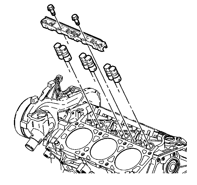
For 1990-2009 cars only
Removal Procedure
- Drain the coolant.
- Remove the coolant recovery reservoir. Refer to SECTION 6B.
- Remove the accessory drive belt. Refer to Drive Belt Replacement .
- Remove the upper intake manifold. Refer to Upper Intake Manifold Replacement .
- Remove the lower intake manifold. Refer to Lower Intake Manifold Replacement .
- Remove the valve rocker arms and pushrods. Refer to Valve Rocker Arm and Push Rod Replacement .
- Remove the lifter guide bolts.
- Remove the lifter guide.
- Remove the lifter.

Installation Procedure
- Coat the lifters with prelube, GM P/N 1052365 or equivalent.
- Install the lifters to the same location from which they were removed.
- Install the lifter guide.
- Install the lifter guide bolts.
- Install the valve rocker arms and pushrods. Refer to Valve Rocker Arm and Push Rod Replacement .
- Install the lower intake manifold. Refer to Lower Intake Manifold Replacement .
- Instal the upper intake manifold. Refer to Upper Intake Manifold Replacement .
- Install the accessory drive belt. Refer to Drive Belt Replacement .
- Install the coolant recovery reservoir. Refer to SECTION 6B.
- Refill the engine with coolant. Add two engine coolant sealant pellets, GM P/N 3634621 or the equivalent.
- Bleed the engine cooling system. Refer to SECTION 6B.

Tighten
Tighten the bolts to 10 N·m (89 lb in).
Notice: Use the correct fastener in the correct location. Replacement fasteners must be the correct part number for that application. Fasteners requiring replacement or fasteners requiring the use of thread locking compound or sealant are identified in the service procedure. Do not use paints, lubricants, or corrosion inhibitors on fasteners or fastener joint surfaces unless specified. These coatings affect fastener torque and joint clamping force and may damage the fastener. Use the correct tightening sequence and specifications when installing fasteners in order to avoid damage to parts and systems.
