Secondary Air Injection Check Valve and Pipe Replacement Left Bank AIR Check Valve
Removal Procedure
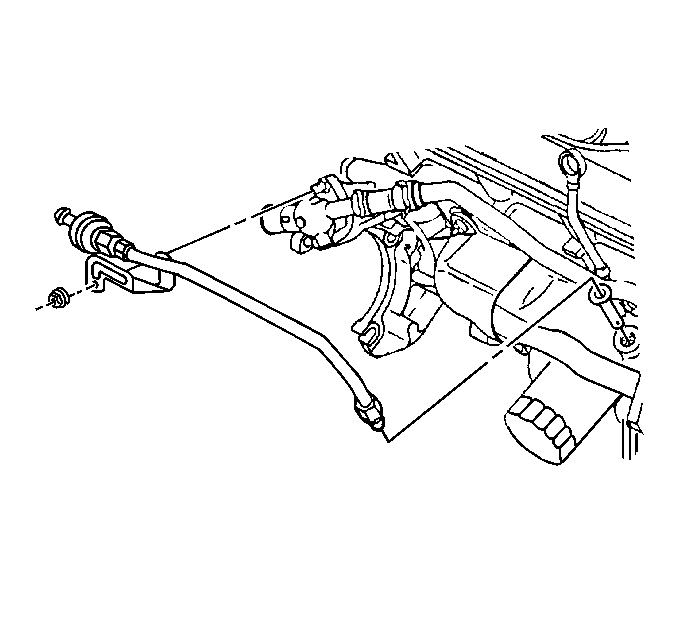
- Remove the hose/clamp assembly from the check valve.
- Remove the retaining nut securing the AIR pipe to the engine block.
- Remove the AIR pipe from the left bank exhaust manifold.
- Remove the AIR check valve from the pipe assembly.

Important: Inspect the exhaust manifold for a missing, plugged or damaged AIR system baffle. If a problem is found, replace as necessary.
Installation Procedure
- Install the AIR Check valve to the pipe assembly.
- Install the AIR pipe assembly to the exhaust manifold.
- Install the retaining nut securing the AIR pipe to the engine block.
- Install the hose/clamp assembly to the check valve.

Tighten:
Torque the assembly to 25 N·m (18 lb. ft.).
Tighten:
Torque the nut to 35 N·m (26 lb. ft.).
Tighten:
Torque the nut to 10 N·m (8 lb. ft.).
Secondary Air Injection Check Valve and Pipe Replacement Right Bank AIR Check Valve
Notice: On-vehicle service of the Right Bank AIR Check Valve requires lowering the engine cradle. Refer to On-Vehicle Service, Power Rack and Pinion Assembly in Section 3B.
Removal Procedure
- Raise the vehicle.
- Remove the left and right front wheel assemblies.
- Lower the vehicle frame. Refer to Power Rack and Pinion service procedures in Steering/Suspension.
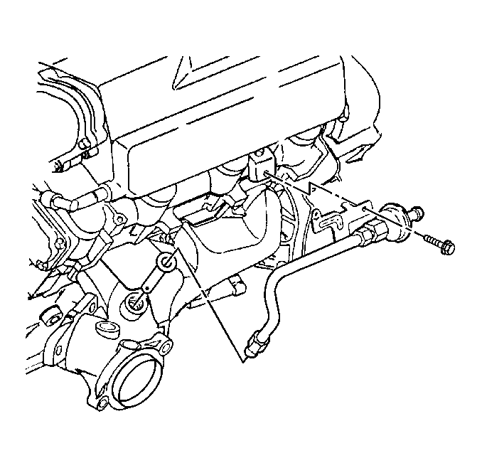
- Remove the hose/clamp assembly from the check valve.
- Remove the retaining bolt from the AIR pipe support bracket.
- Remove the right AIR pipe assembly from the exhaust manifold.
- Remove the right bank AIR Check valve from the pipe assembly.

Important: Inspect the exhaust for a missing, plugged or damaged AIR system baffle. If a problem is found, replace as necessary.
Installation Procedure
- Install the right bank AIR check valve to the AIR pipe assembly.
- Install the right AIR pipe assembly to the exhaust manifold.
- Install the retaining bolt for the AIR pipe support bracket.
- Install the hose/clamp assembly to the check valve.
- Raise the vehicle frame. Refer to Power Rack and Pinion Service procedures in Steering/Suspension.
- Install the left and right front wheel assemblies.
- Lower the vehicle.

Tighten:
Torque the assembly to 25 N·m (18 lb. ft.).
Tighten:
Torque the nut to 35 N·m (26 lb. ft.).
Tighten:
Torque the nut to 10 N·m (8 lb. ft.).
Tighten:
Torque the wheel lug nuts to 140 N·m (104 lb. ft.)
Secondary Air Injection Check Valve and Pipe Replacement AIR Pipes
Removal Procedure
- Raise the vehicle.
- Remove the right front wheel assembly.
- Remove the right inner fender access cover.
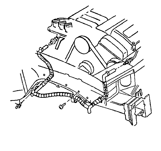
- Remove the hose/clamp from the right bank check valve.
- Remove the hose/clamp from the left bank check valve.
- Remove the feed pipe assembly retaining clips and bolts.
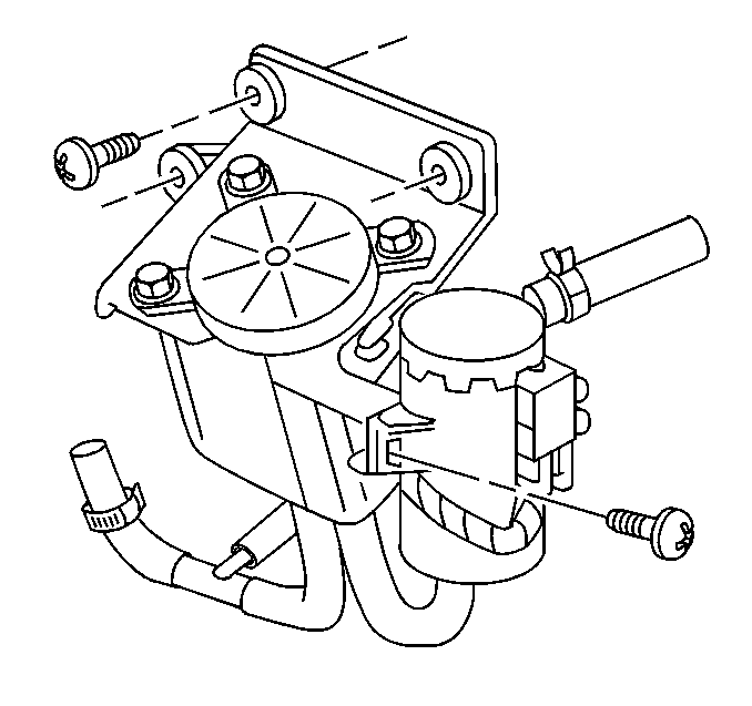
- Remove the hose/clamp connecting the AIR feed pipe assembly to the AIR pump.
- Remove the feed pipe assembly.

Installation Procedure
- Install the AIR feed pipe assembly.
- Install the feed pipe assembly retaining clips and bolts.
- Install the hose/clamp to the left bank check valve.
- Install the hose/clamp to the right bank check valve.
- Install the hose/clamp connecting the AIR feed pipe to the AIR pump assembly.
- Install the right inner fender access cover.
- Install the right front wheel and tire assembly.
- Lower the vehicle.

Tighten:
Torque the bolts to 8 N·m (70 lb. in.)

Tighten:
Torque the wheel lug nuts to 140 N·m (104 lb. ft.)
