Fuel Hose and Pipes Tank to Filter
Removal Procedure
Caution: In order to Reduce the Risk of Fire and Personal Injury:
• If nylon fuel pipes are nicked, scratched or damaged during installation,
Do Not attempt to repair the sections of the nylon fuel pipes. Replace them. • When installing new fuel pipes, Do Not hammer directly on the
fuel harness body clips as it may damage the nylon pipes resulting in a possible
fuel leak. • Always cover nylon vapor pipes with a wet towel before using a
torch near them. Also, never expose the vehicle to temperatures higher than
115°C (239°F) for more than one hour, or more than 90°C (194°F)
for any extended period. • Before connecting fuel pipe fittings, always apply a few drops
of clean engine oil to the male pipe ends. This will ensure proper reconnection
and prevent a possible fuel leak. (During normal operation, the O-rings located
in the female connector will swell and may prevent proper reconnection if
not lubricated.)
Notice: Do not attempt to straighten any kinked nylon fuel lines. Replace any kinked nylon fuel feed or return pipes in order to prevent damage to the vehicle.
- Relieve the fuel system fuel pressure. Refer to Fuel Pressure Relief W 3800, Fuel Pressure Relief W 3100, Fuel Pressure Relief W 3.4L.
- Drain the fuel tank. Refer to Fuel Tank Draining Procedure W 3800, Fuel Tank Draining W 3100, Fuel Tank Draining Procedure W 3.4L.
- Remove the fuel tank. Refer to Fuel Tank Replacement ,W 3800 Fuel Tank Replacement W 3100, Fuel Tank Replacement W 3.4L.
- Remove the quick-connect fittings on the fuel sender assembly side of the in-pipe fuel. Refer to Servicing Quick Connect Fittings W 3800, Servicing Quick Connect Fittings W 3100, Servicing Quick Connect Fittings W 3.4L.
- Cap the fuel sender fuel pipes and the in-pipe fuel filter pipes as needed to stop any fuel leakage.
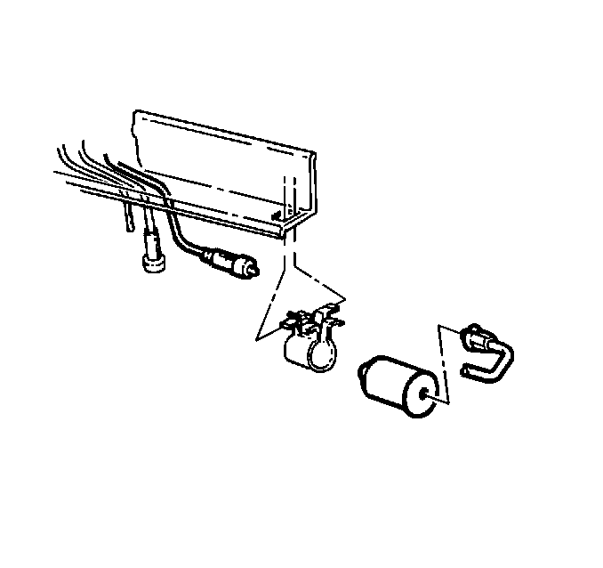
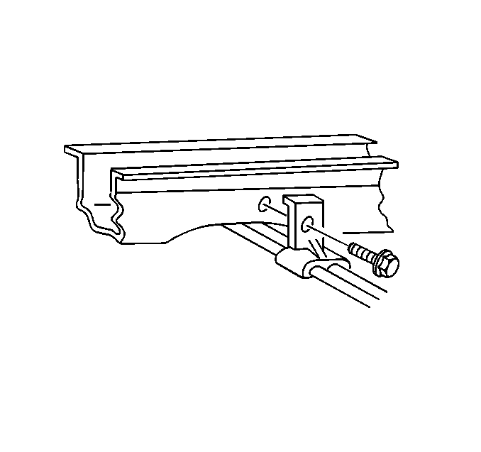
- Remove the fuel feed, fuel return, and EVAP pipe attaching hardware and the fuel feed, fuel return, and EVAP pipes.
- Note the position of the fuel and EVAP pipes and the fuel and EVAP pipe attaching hardware for installation.
Installation Procedure
Caution: In order to Reduce the Risk of Fire and Personal Injury: If nylon fuel pipes are nicked, scratched or damaged during installation, they must be replaced.
- Install the new fuel feed, fuel return, and EVAP pipes and the fuel and EVAP pipe attaching hardware as noted during removal.
- Remove the caps from the in-pipe fuel filter pipes and the fuel sender fuel pipes.
- New plastic connector retainers on the in-pipe fuel filter pipes and on the fuel sender fuel pipes.
- Install the quick-connect fittings. Refer to Servicing Quick Connect Fittings W 3800, Servicing Quick Connect Fittings W 3100, Servicing Quick Connect Fittings W 3.4L.
- Install the fuel tank. Refer to Fuel Tank Replacement W 3800, Fuel Tank Replacement W 3100, Fuel Tank Replacement W 3.4L.
- Add fuel and install the fuel tank filler pipe cap.
- Tighten the fuel tank filler pipe cap.
- Install the negative battery cable.
- Inspect for leaks.


| 9.1. | Turn the ignition switch to the ON position for two seconds. |
| 9.2. | Turn the ignition switch to the OFF for ten seconds. |
| 9.3. | Turn the ignition switch to the ON position again. |
| 9.4. | Check for fuel leaks. |
Fuel Hose and Pipes Filter to Engine
Removal Procedure
Tool Required
J 37088-A tool set, Fuel Pipe Quick-Connect Separator
Caution: In order to Reduce the Risk of Fire and Personal Injury:
• If nylon fuel pipes are nicked, scratched or damaged during installation,
Do Not attempt to repair the sections of the nylon fuel pipes. Replace them. • When installing new fuel pipes, Do Not hammer directly on the
fuel harness body clips as it may damage the nylon pipes resulting in a possible
fuel leak. • Always cover nylon vapor pipes with a wet towel before using a
torch near them. Also, never expose the vehicle to temperatures higher than
115°C (239°F) for more than one hour, or more than 90°C (194°F)
for any extended period. • Before connecting fuel pipe fittings, always apply a few drops
of clean engine oil to the male pipe ends. This will ensure proper reconnection
and prevent a possible fuel leak. (During normal operation, the O-rings located
in the female connector will swell and may prevent proper reconnection if
not lubricated.)
Notice: Do not attempt to straighten any kinked nylon fuel lines. Replace any kinked nylon fuel feed or return pipes in order to prevent damage to the vehicle.
Notice: Replace the EVAP pipes and hoses with the original equipment or parts that meet the GM specifications for those parts. The replacement EVAP pipe must have the same type of fittings as the original pipe in order to ensure the integrity of the connection. When replacing EVAP hoses, use only reinforced fuel-resistant hose identified with the word Fluoroelastomer or GM 6163-M on the hose. The inside hose diameter must match the outside pipe diameter. Do not use rubber hose within 100 mm (4 in) of any part of the exhaust system or within 254 mm (10 in) of the catalytic converter.
- Relieve the fuel system fuel pressure. Refer to Fuel Pressure Relief W 3800, Fuel Pressure Relief W 3100, Fuel Pressure Relief W 3.4L.
- Clean all engine fuel pipe connections.
- Clean areas surrounding the engine fuel pipe connections.
- Remove the quick-connect fittings in the engine compartment. Refer to Servicing Quick Connect Fittings W 3800, Servicing Quick Connect Fittings W 3100, Servicing Quick Connect Fittings W 3.4L.
- Raise the vehicle.
- Remove the quick-connect fitting on the engine-side of the in-pipe fuel filter fuel return pipe. Refer to .Servicing Quick Connect Fittings W 3800, Servicing Quick Connect Fittings W 3100, Servicing Quick Connect Fittings W 3.4L.
- Remove the threaded fitting on the engine-side of the in-pipe fuel filter fuel feed pipe.
- Cap the in-pipe fuel filter pipe, the fuel feed pipe, and the fuel return pipe as needed to stop any fuel leakage.
- Remove the fuel feed, fuel return, and EVAP pipe attaching hardware and the fuel feed, fuel return, and EVAP pipes.
- Note the position of the fuel and EVAP pipes and the fuel and EVAP pipe attaching hardware for installation.
- Inspect the pipes for bends, kinks and cracks.
- Repair or replace the pipe or pipes as required.
- In the repairable areas, cut a piece of fuel hose 100 mm (4 in.) longer than portion of the pipe removed.
- If more than a 152 mm (6 in.) length of pipe is removed, use a combination of steel pipe and hose so that the total hose lengths, including the 100 mm (4 in.) additional length will not be more than 254 mm (10 in.) long.
Installation Procedure
Caution: In order to Reduce the Risk of Fire and Personal Injury: If nylon fuel pipes are nicked, scratched or damaged during installation, they must be replaced.
- Install the new fuel feed, fuel return, and EVAP pipes and the fuel and EVAP pipe attaching hardware as noted during removal.
- Remove the caps from the in-pipe fuel filter pipe, the fuel feed pipe, and the fuel return pipe.
- New plastic connector retainers on the fuel return pipes.
- Install the quick-connect fitting at the in-pipe fuel filter in the fuel return pipe. Refer to Servicing Quick Connect Fittings W 3800, Servicing Quick Connect Fittings W 3100, Servicing Quick Connect Fittings W 3.4L.
- Install the threaded fitting at the outlet of the in pipe fuel filter in the fuel feed pipe.
- Lower the vehicle.
- Install the quick-connect fittings in the engine compartment Refer to Servicing Quick Connect Fittings W 3800, Servicing Quick Connect Fittings W 3100, Servicing Quick Connect Fittings W 3.4L.
- Add fuel and install the fuel tank filler pipe cap.
- Tighten the fuel tank filler pipe cap.
- Install the negative battery cable.
- Inspect for leaks.
Tighten
Tighten The in-pipe fuel filter fitting to 30 N·m (22
lb. ft.).
| 11.1. | Turn the ignition switch to the ON position for two seconds. |
| 11.2. | Turn the ignition switch to the OFF for ten seconds. |
| 11.3. | Turn the ignition switch to the ON position again. |
| 11.4. | Check for fuel leaks. |
Fuel Hose and Pipes EVAP
Removal Procedure
Notice: Do Not attempt to repair the EVAP pipes or the connecting hoses. Replace the damaged EVAP pipes or the connecting hoses are damaged. If the nylon EVAP pipe becomes kinked and cannot be straightened, it must be replaced.
Notice: Replace the EVAP pipes and hoses with the original equipment or parts that meet the GM specifications for those parts. The replacement EVAP pipe must have the same type of fittings as the original pipe in order to ensure the integrity of the connection. When replacing EVAP hoses, use only reinforced fuel-resistant hose identified with the word Fluoroelastomer or GM 6163-M on the hose. The inside hose diameter must match the outside pipe diameter. Do not use rubber hose within 100 mm (4 in) of any part of the exhaust system or within 254 mm (10 in) of the catalytic converter.
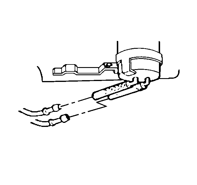
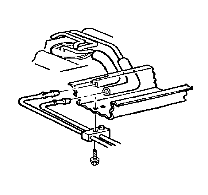
- Remove the hardware retaining the EVAP pipes. Note the location of the attaching hardware for installation.
- Remove the EVAP pipes at the EVAP canister.
- Remove the EVAP pipes at the fuel tank
- Remove the EVAP pipes.

Installation Procedure
Important: Route the replacement EVAP pipe in the same manner as the original EVAP pipe was routed.
- Install the EVAP pipes into the vehicle.
- Install the EVAP pipes onto the fuel tank.
- Install the EVAP pipes onto the EVAP canister.
- Install the hardware retaining the EVAP pipe.


Notice: Properly secure the EVAP pipe in order to prevent chafing of the pipe.

Fuel Hose and Pipes Engine
Removal Procedure
Caution: In order to Reduce the Risk of Fire and Personal Injury:
• If nylon fuel pipes are nicked, scratched or damaged during installation,
Do Not attempt to repair the sections of the nylon fuel pipes. Replace them. • When installing new fuel pipes, Do Not hammer directly on the
fuel harness body clips as it may damage the nylon pipes resulting in a possible
fuel leak. • Always cover nylon vapor pipes with a wet towel before using a
torch near them. Also, never expose the vehicle to temperatures higher than
115°C (239°F) for more than one hour, or more than 90°C (194°F)
for any extended period. • Before connecting fuel pipe fittings, always apply a few drops
of clean engine oil to the male pipe ends. This will ensure proper reconnection
and prevent a possible fuel leak. (During normal operation, the O-rings located
in the female connector will swell and may prevent proper reconnection if
not lubricated.)
Caution: In order to reduce the risk of fire and personal injury, before connecting fuel pipe fittings, always apply a few drops of clean engine oil to the male pipe ends.
This will ensure proper reconnection and prevent a possible fuel leak. During normal operation, the O-rings located in the female connector will swell and may prevent proper reconnection if not lubricated.- Relieve fuel system pressure. Refer to Fuel Pressure Relief .
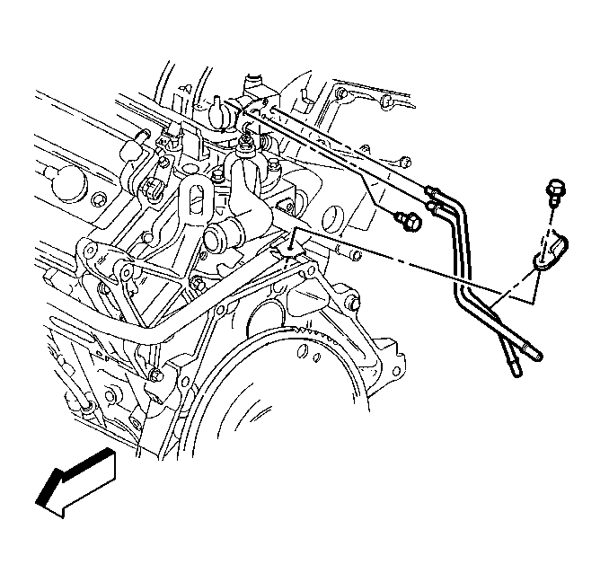
- Remove the fuel feed and return pipes from the fuel rail tubes by squeezing tabs and pulling the lines apart.
- Remove the fuel pipe retaining clip bolt and clip holding lines to engine block.
- Remove the fuel pipes to fuel rail retaining screws and retainer.
- Remove the fuel feed and return pipes from the fuel rail.
- Remove the fuel feed and return pipe O-rings and discard.
Installation Procedure
- New O-rings on the engine fuel feed and return pipes.
- Install the fuel feed and return pipes to the fuel rail.
- Install the fuel pipes to fuel rail retaining screws and retainer.
- Install the fuel pipe retaining clip bolt and clip holding lines to engine block.
- Install the fuel filler cap.
- Install the fuel feed and return pipes to the fuel rail tubes.

Tighten
Tighten the fuel pipe retainer and screws to 3.0 N·m(27 lb.
in.).
Tighten
Tighten the fuel pipe retaining clip bolt at engine block to 3.0 N·m(27 lb.
in.).
