Tools Required
| • | J 8001 Dial Indicator Set |
| • | J 8087 Cylinder Bore Checking Gauge |
- Clean the sealing material from the mating surfaces.
- Boil in caustic solution.
- Flush with clean water or steam.
- Clean the oil passages.
- Clean all of the blind holes.
- Spray or wipe the cylinder bores and machined surfaces with engine oil.
- Check the surface for flatness. Use a straight edge and a feeler gauge. If the cylinder head deck flatness exceeds 0.1 mm (0.004 in), the surface should be machined flat. If more than 0.25 mm (0.010 in) must be removed, replace the block.
- Inspect the oil pan rail and timing cover attaching area for nicks. Minor irregularities may be cleaned up with a flat mill file.
- Inspect the head bolt tapped holes.
- Inspect the transaxle case mating surface.
- Measure the crankshaft runout. With the crankshaft installed, place a dial indicator stem just outside the flywheel mounting bolt holes. Set the indicator to 0. Rotate the crankshaft and record the readings. If the readings are not within limits, the crankshaft must be replaced.
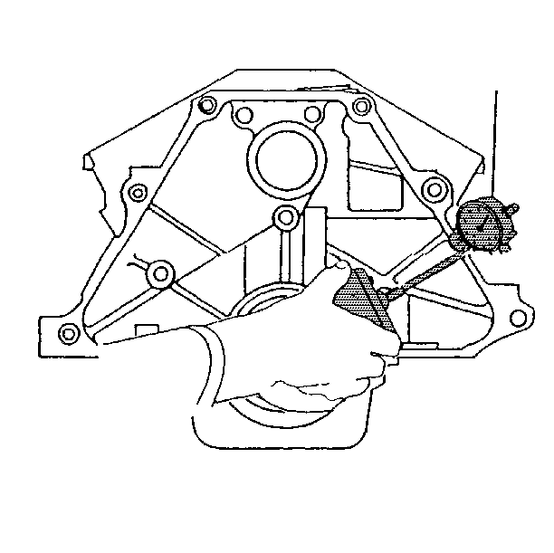
- Use the following procedure in order to measure the cylinder block flange surface runout at six mounting hole bosses.
- Place a dial indicator stem on the transaxle mounting bolt hole boss and set the indicator to 0.
- Take and record the readings obtained on the remaining transaxle mounting bolt hole bosses. Measurements should not vary more than 0.25 mm (0.010 in).
- If the readings vary more than 0.25 mm (0.010 in), recheck the crankshaft flange runout. Replace the crankshaft if the runout is excessive.
- Inspect the threaded holes. If necessary, clean with a tap or drill out and install the thread inserts.
- Inspect the intermediate shaft and crankshaft bearing bores. Use the J 8087 in order to measure the concentricity and alignment.
- Inspect the cylinder bore. Use the J 8087 in order to measure for wear, taper, or runout and ridging.
- If the bore is worn out of specifications it may be rebored, honed and fitted with oversize pistons. The smallest available oversized should be selected.
Important: Caustic cleaning solution destroys the bearing material. All bearings must be replaced after cleaning with a caustic cleaning solution. Do not clean bearing material or aluminum parts with caustic solutions.
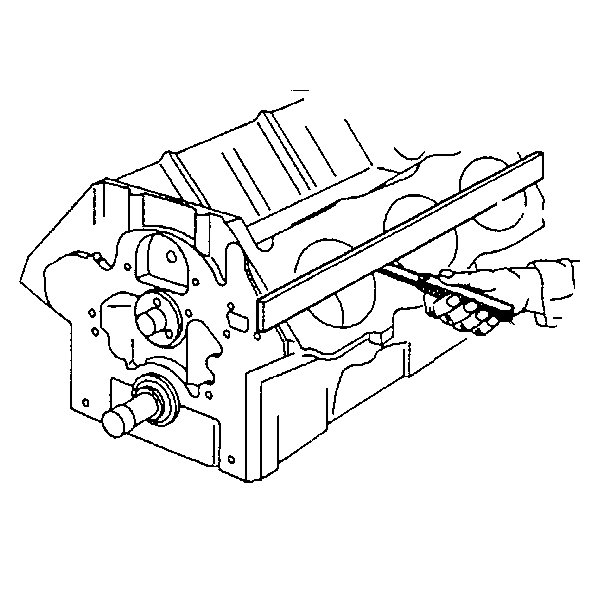
Notice: A broken flywheel may result if the transmission case mating surface is not flat.
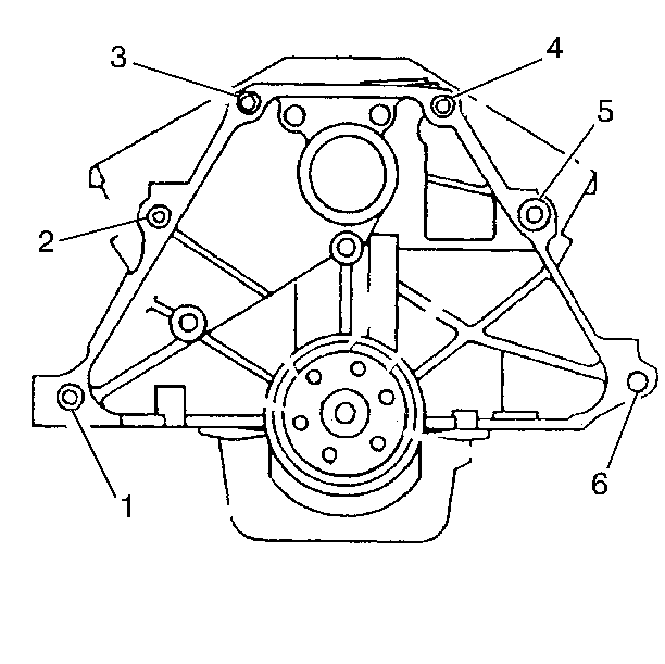
Important: The following inspections as well as reconditioning, must be carried out with the main bearing caps installed and tightened to specification. Ensure that the main bearing caps are installed correctly, with the arrows pointing toward the front of the engine.
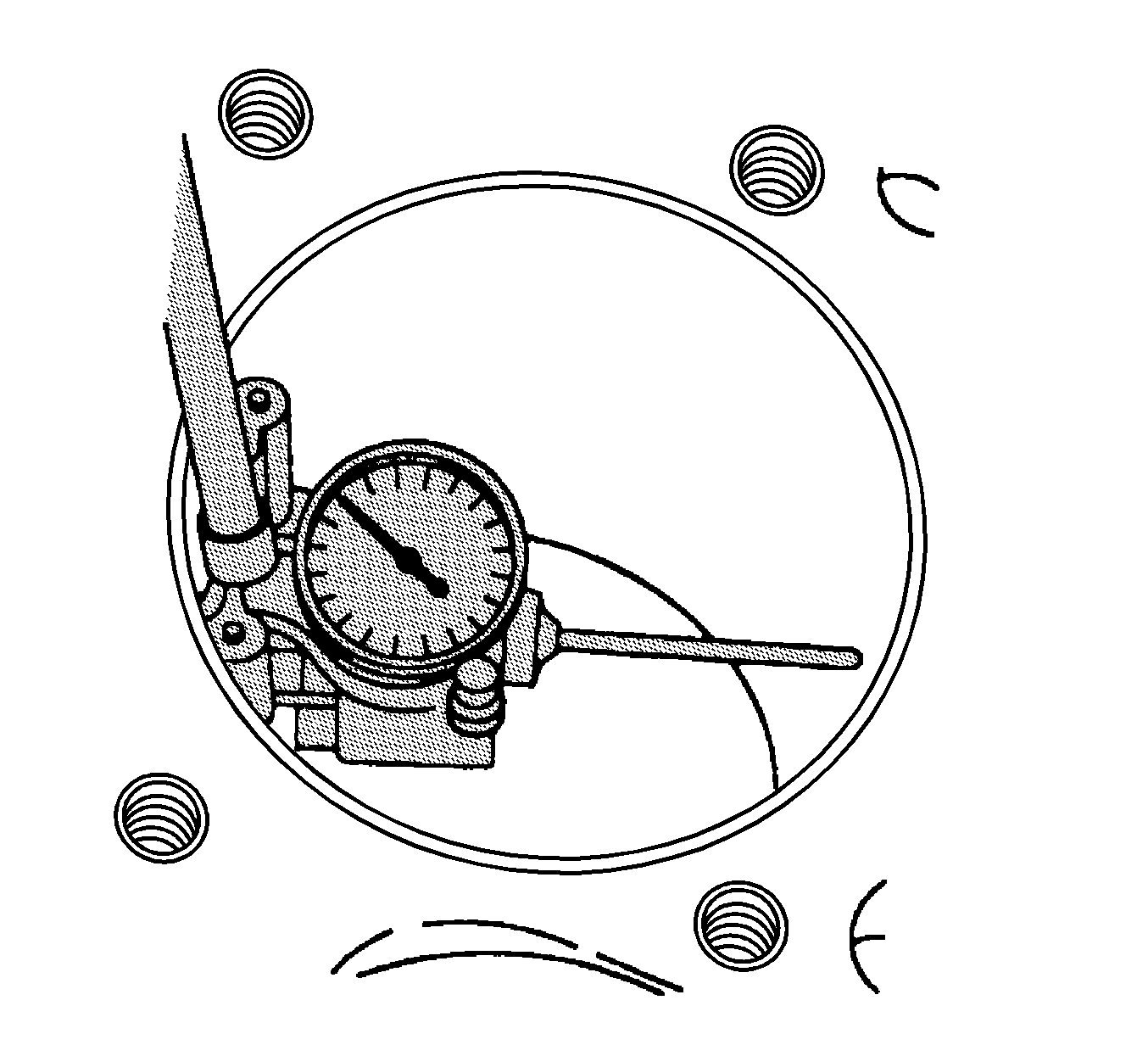
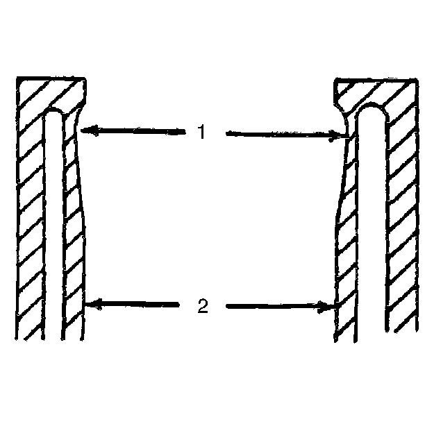
Important: Leave sufficient material in order to allow finish honing in conjunction with fitting the piston. If the bore is glazed but otherwise serviceable, break the glaze lightly with a hone and replace the piston rings. Ensure that the honing stones are clean, sharp and straight. Move the hone slowly up and down in order to produce a cross-hatch pattern. Clean the bore thoroughly with soap and water. Dry and rub in clean engine oil, then remeasure.
