Caution: Bodily injury may occur if carburetor cleaning fluid is exposed to the
skin or if the fumes are inhaled.
- Clean the following components of sludge and carbon:
- Clean the piston ring grooves of carbon to the bare metal.
- Clean any varnish from the piston pin. Do this by soaking the
piston pin in a carburetor cleaning solution. Do not scrape the piston skirt.
- Inspect the connecting rod for bending or twisting using the following
procedure:
| 4.1. | Install the connecting rod cap. |
| 4.2. | Place the connecting rod assembly on a checking fixture. Check
for bending or twisting. |
| 4.3. | Do not attempt to straighten the connecting rod. If the connecting
rod is bent or twisted, replace the connecting rod. |
| • | The connecting rods should not be bent more than 0.18 mm
(0.007 in) for every 76.2 mm (3.00 in) of rod length. |
| • | The connecting rods should not be twisted more than 0.038 mm
(0.0015 in) for every 25.4 mm (1.00 in) of rod length. |
| 4.4. | Check new connecting rods before using them. |
- Inspect the outside of the connecting rod bearing and the ID of
the connecting rod lower end for wear indicating high spots in the connecting
rod lower end.
- Inspect the upper end of the connecting rod for scoring.
- Inspect the piston pin for the following conditions:
| • | Galling caused by improper installation |
| • | Fit in connecting rod and piston |
- Inspect the piston for the following conditions:
| • | Broken ring groove lands |

Important: When fitting pistons, both the piston and the cylinder bore condition
must be considered together. Production and service pistons have the same
nominal weight and can be intermixed without affecting engine balance. If
necessary, used pistons may be fitted selectively to any cylinder of the engine,
providing they are in good condition and the same weight.
Do not cut oversize pistons down or the engine balance will be affected.
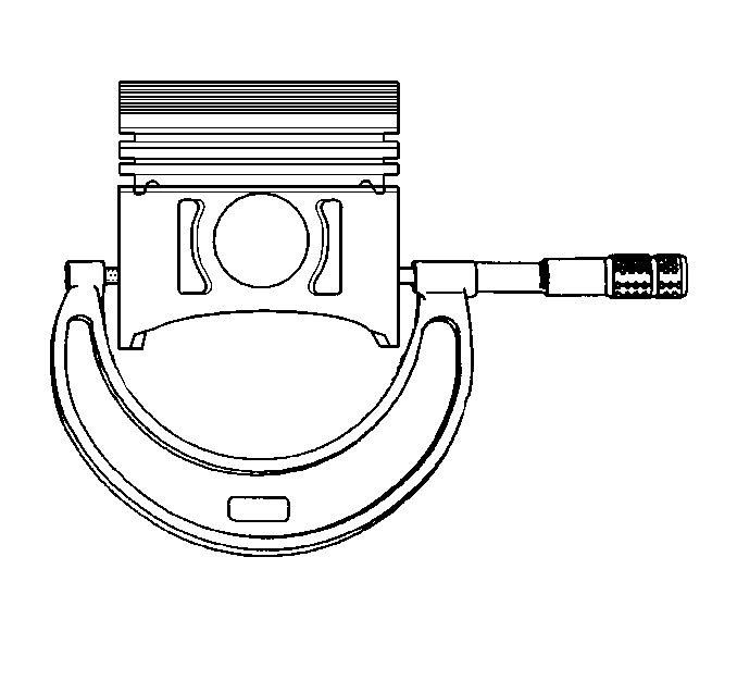
- Measure the piston diameter.
- When measuring the piston for size or taper, make the measurement
with the piston pin removed. If the piston is worn or damaged, replace the
piston with a standard or oversize piston.

Important: Finish hone when selecting the piston.
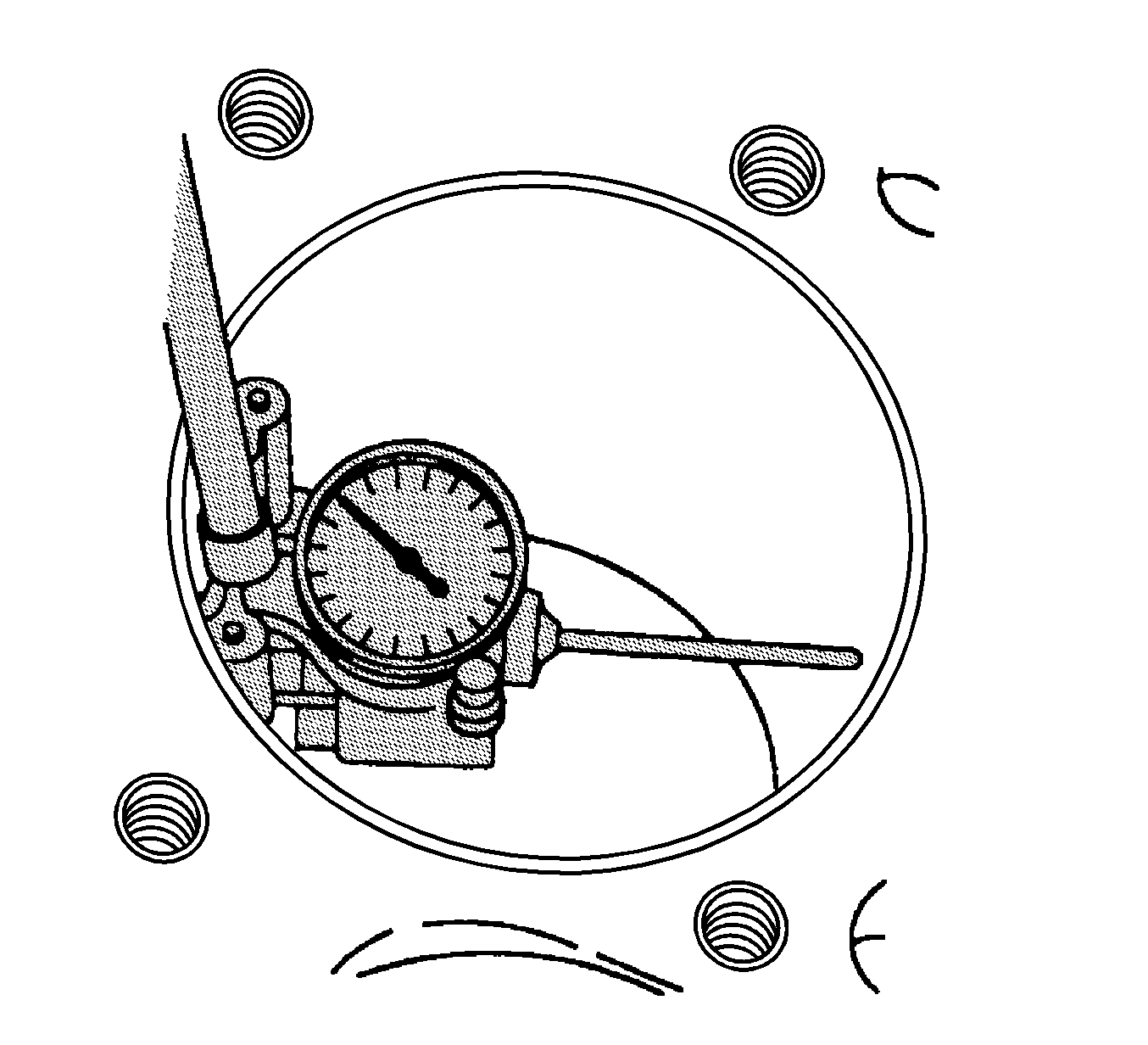
- Measure the cylinder bore with a telescoping gage. If the cylinder bore
is worn beyond specifications, rebore and hone the cylinder bore to size.
- Subtract the piston diameter from the cylinder bore diameter to
determine the piston-to-bore clearance. Refer to Engine Mechanical Specifications
.
- Compare the piston-to-bore clearance with the specifications in
order to determine if the clearance is in the acceptable range.
- If the used piston is not acceptable, check the service piston
sizes. Determine if a new piston can be selected. Service pistons are available
in standard, and several oversizes.
- If you must recondition the cylinder bore, measure the new piston
diameter. Then hone the cylinder bore to the correct clearance.
- Select a new piston.
- Mark the piston in order to identify the cylinder for which the
piston was fitted.
- Measure the piston pin bore diameter with an inside micrometer.
- Measure the piston pin diameter with a micrometer.
- Subtract the piston pin bore diameter from the piston pin diameter
in order to determine the clearance. Refer to Engine Mechanical Specifications
.
- If the clearance is not acceptable, replace the piston assembly.

Important: Do not reuse piston rings. Fit rings to match the cylinder they will
be used in.
- Measure the piston compression ring end gap using the following procedure:
| 22.1. | Place the piston into the cylinder at the bottom of the ring travel. |
| 22.2. | Place a piston ring on top of the piston. |
| 22.3. | Back off the piston. |
| 22.4. | Measure the ring gap. If the gap is below specification, increase
the gap by carefully filing off excess material. Refer to Engine Mechanical Specifications
. |
Important: Do not attempt to cut the ring groove, although high spots in the ring
groove may be cleaned up by careful use of a point file.
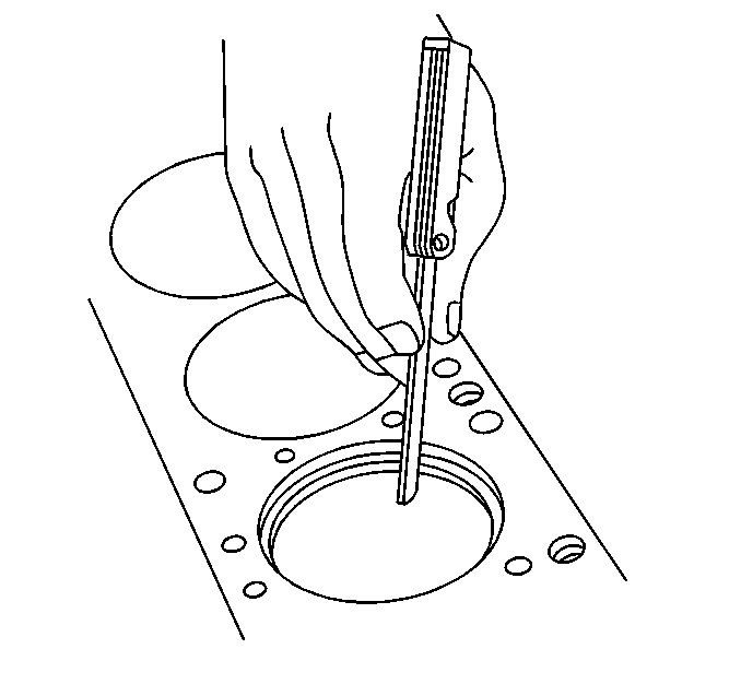
- Measure the piston compression ring side clearance using the following
procedure:
| 23.1. | Roll the piston ring around the groove in which it is to be installed. |
| 23.2. | Measure the side clearance. If the ring is too thick, try another
ring. Refer to Engine Mechanical Specifications
. |


