Tools Required
J 38612 Crankshaft
Sprocket Installer

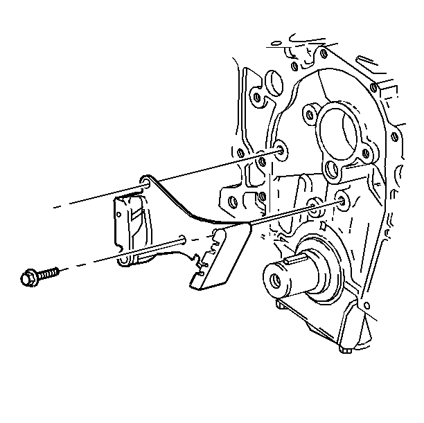
- Install the tensioner to the engine block.
- Use the upper attaching hole as the primary locator with the attaching
bolt.
Tighten
- Tighten all bolts finger tight.
- Tighten the slotted hole bolt first to 27 N·m (20 lb ft).
- Tighten the other bolts to 25 N·m (18 lb ft).
Notice: Use the correct fastener in the correct location. Replacement fasteners
must be the correct part number for that application. Fasteners requiring
replacement or fasteners requiring the use of thread locking compound or sealant
are identified in the service procedure. Do not use paints, lubricants, or
corrosion inhibitors on fasteners or fastener joint surfaces unless specified.
These coatings affect fastener torque and joint clamping force and may damage
the fastener. Use the correct tightening sequence and specifications when
installing fasteners in order to avoid damage to parts and systems.

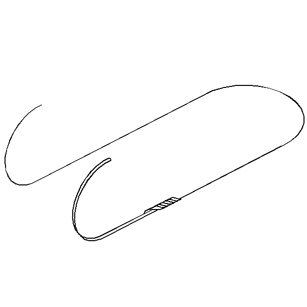
- In order to retract the tensioner, fabricate a tool using the following procedure:
| 3.1. | Bend a 16 inch piece of 1/8 inch welding rod or
equivalent in half, leaving a 1 inch gap between the two ends. |
| 3.2. | Make a bend 1 inch from the end, perpendicular to the original
bend, at 60°. |
| 3.3. | Repeat this process for the other end. Make sure both ends are
bent in the same direction. |

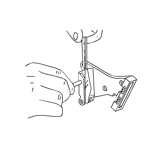
- Engage under the tensioner with the tool.
- Compress the spring with the tool.
- Retract the tensioner.
- Insert a cotter pin, rivet or nail into the hole. Ensure that
the spring remains compressed.
- Lightly oil or apply lithium grease to the chain contact surfaces
of the nylon pad and blade.
- Make sure the crankshaft key is installed and fully seated.

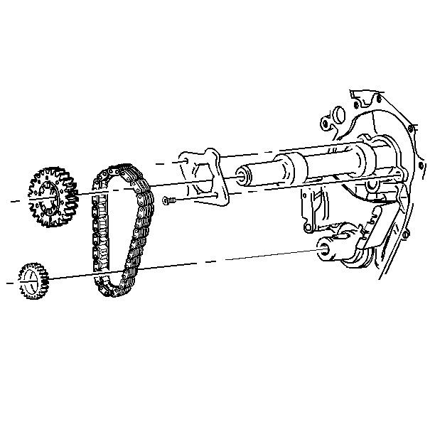
- Slip both the sprockets and the chain over the proper shaft. Engage the slot
in the key. The intermediate shaft may move against the rear cover.
- Slide the sprocket and chain assembly on the shafts maintaining
parallel alignment of the sprockets. Install the assembly in the following
positions:
| • | Make sure the rubber and tension blade of the tensioner does not
become caught, misaligned or dislodged. |
| • | Install the larger chamfer and counterbore of the crankshaft sprocket
toward the crankshaft. The intermediate sprocket spline sockets are installed
away from the case. |
| • | Use the J 38612
in
order to press the crankshaft sprocket on for the final 8 mm (0.31 in)
to the seated position. |
- Pull the retaining pin from the tensioner.


