Starter Replacement 3100 Engine L82
Removal Procedure
- Disconnect the negative battery cable. Refer to
Caution: Unless directed otherwise, the ignition and start switch must be in the OFF or LOCK position, and all electrical loads must be OFF before servicing any electrical component. Disconnect the negative battery cable to prevent an electrical spark should a tool or equipment come in contact with an exposed electrical terminal. Failure to follow these precautions may result in personal injury and/or damage to the vehicle or its components.
in General Information. - Remove the air cleaner and the duct.
- Raise and suitably support the vehicle. Refer to Section 0A.
- Remove the oil filter splash shield.
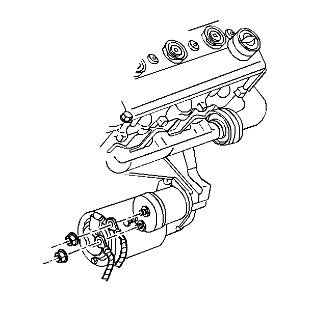
- Remove the electrical connections at the starter.
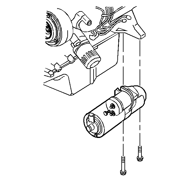
- Remove the starter motor mounting bolts. Remove the shims, if necessary.
- Remove the starter motor from the engine.

Installation Procedure
- Install the starter motor to the engine.
- Install the starter motor mounting bolts and the shims, if necessary.
- Install the electrical connections to the starter.
- Install the oil splash shield.
- Lower vehicle.
- Install the air cleaner and the duct.
- Connect the negative battery cable.

Tighten
Tighten the bolts to 43 N·m (32 lb ft).
Tighten
| • | Tighten the starter solenoid switch BAT terminal outer nut to 9.5 N·m (84 lb in). |
| • | Tighten the starter solenoid switch S terminal nut to 2.5 N·m (22 lb in). |
Starter Replacement 3.4L Engine LQ1
Removal Procedure
Important: The 3.4L engine uses the PG260M starter motor. This starter motor is serviced as a unit.
- Disconnect the negative battery cable. Refer to
Caution: Unless directed otherwise, the ignition and start switch must be in the OFF or LOCK position, and all electrical loads must be OFF before servicing any electrical component. Disconnect the negative battery cable to prevent an electrical spark should a tool or equipment come in contact with an exposed electrical terminal. Failure to follow these precautions may result in personal injury and/or damage to the vehicle or its components.
in General Information. - Remove the engine oil cooler. Refer to Cooling and Radiator.
- Remove the flywheel inspection cover bolts.
- Remove the flywheel inspection cover.
- Remove the electrical connections from the starter motor.
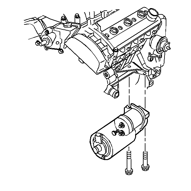
- Remove the starter motor mounting bolts.
- Remove the starter motor.


Installation Procedure
- Secure the electrical terminal on the solenoid.
- Install the electrical connections to the starter motor.
- Install the starter motor to the engine.
- Install the starter motor mounting bolts.
- Install the flywheel inspection cover.
- Install the flywheel inspection cover bolts.
- Install the engine oil cooler. Refer to Cooling and Radiator.
- Connect the negative battery cable.
Notice: Before installing the starter motor to the engine, tighten the nut next to the cap on the solenoid BAT terminal. If this terminal is not tight in the solenoid cap, the cap may be damaged during installation of electrical connections and cause the starter motor to fail later.

Tighten
Tighten the solenoid battery terminal inside nut to 9.5 N·m
(84 lb in).
Tighten
| • | Tighten the solenoid battery terminal outside the nut to 9.5 N·m (84 lb in). |
| • | Tighten solenoid S terminal outside the nut to 2.5 N·m (22 lb in). |

Tighten
Tighten the starter motor mounting bolts to 43 N·m (32 lb ft).
Tighten
Tighten the bolts to 10 N·m (89 lb in).
Tighten
Tighten the cable bolt to 15 N·m (11 lb ft).
Starter Replacement 3800 Engine L36
Removal Procedure
- Disconnect the negative battery cable. Refer to
Caution: Unless directed otherwise, the ignition and start switch must be in the OFF or LOCK position, and all electrical loads must be OFF before servicing any electrical component. Disconnect the negative battery cable to prevent an electrical spark should a tool or equipment come in contact with an exposed electrical terminal. Failure to follow these precautions may result in personal injury and/or damage to the vehicle or its components.
in General Information. - Remove the upper mounting bracket above the radiator.
- Remove the electrical connections at the coolant fan.
- Remove the coolant fan.
- Remove the upper and the lower oil cooler pipes from the radiator.
- Raise and suitably support the vehicle. Refer to Section 0A.
- Remove the retainers from the engine harness and reposition away from the starter.
- Remove both of the lower oil cooler hoses from the radiator.
- Remove the starter electrical connections.
- Remove the upper flywheel inspection cover.
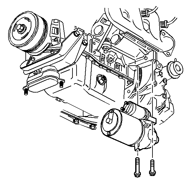
- Remove the mounting bolts.
- Remove the starter from the engine and the shims, if necessary.

Installation Procedure
- Install the starter to the engine and the shims, if necessary.
- Install the mounting bolts.
- Install the electrical connections to the starter.
- Install the upper inspection cover and the bolts to the flywheel.
- Install both lower oil cooler hoses to the radiator.
- Install the engine wire harness and the retainers.
- Lower the vehicle.
- Install the oil cooler pipes to the radiator.
- Install the coolant fan.
- Install the upper engine mounting bracket.
- Add oil as necessary.
- Connect the negative battery cable.

Tighten
Tighten the bolts to 43 N·m (32 lb ft).
Tighten
| • | Tighten the solenoid battery terminal outside nut to 16 N·m (12 lb in). |
| • | Tighten the solenoid S terminal inside nut to 2.5 N·m (22 lb in). |
Tighten
Tighten the bolts to 10 N·m (89 lb in).
Tighten
Tighten the bolts/screws to 43 N·m (32 lb ft).
