Removal Procedure
Tools Required
J 38400 Brake Shoe
Spanner and Spring Remover
Caution: Keep fingers away from rear brake shoe springs to prevent fingers from
being pinched between spring and shoe web or spring and backing plate.
Notice: Do not pry against the splash shield or backing plate in attempt to
free the drum. This will bend the splash shield or backing plate. A bent backing
plate may cause brake chatter and/or pulsation.
Notice: Do not over stretch the adjuster spring. Damage can occur
if the spring is over stretched.
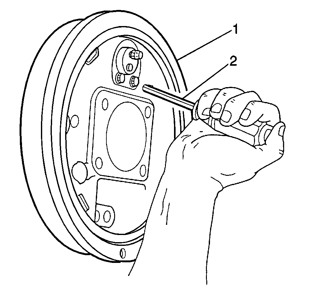
- Raise and suitably support
the vehicle. Refer to
Lifting and Jacking the Vehicle
in General Information.
- Mark the relationship of the wheel to the axle flange.
- Remove the tire and the wheel. Refer to
Tire and Wheel Removal and Installation
in Tires
and Wheels.
- Mark the relationship of the drum to the axle flange.
- Remove the brake drum (1). If difficulty is encountered in removing
the brake drum. Refer to
Brake Drum Replacement
In this section.
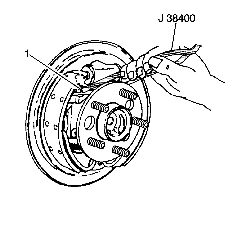
- Remove the adjuster spring
(1). Use the J 38400
in
order to pry the loop end of the adjuster spring from the adjuster actuator.
Then disengage the adjuster spring from the web of the parking brake
shoe.
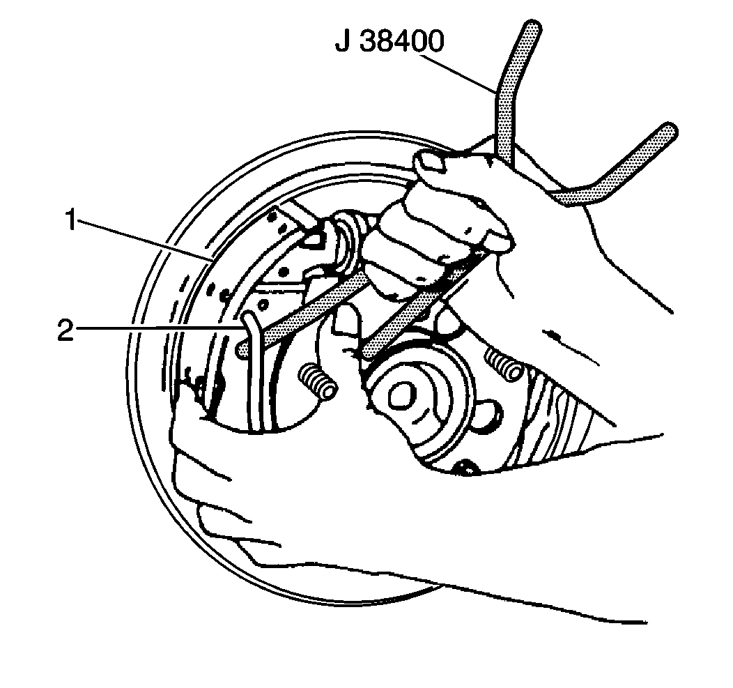
- Remove the lift end of
the return spring (2) from the adjuster shoe and the lining (1).
- Insert the hook end of the J 38400
between the return spring and the adjuster shoe web.
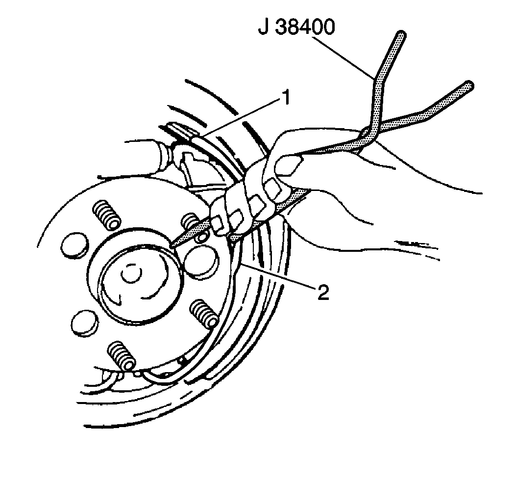
- Pry or twist the J 38400
in order to lift the
end of the spring (2) out of the shoe web hole.
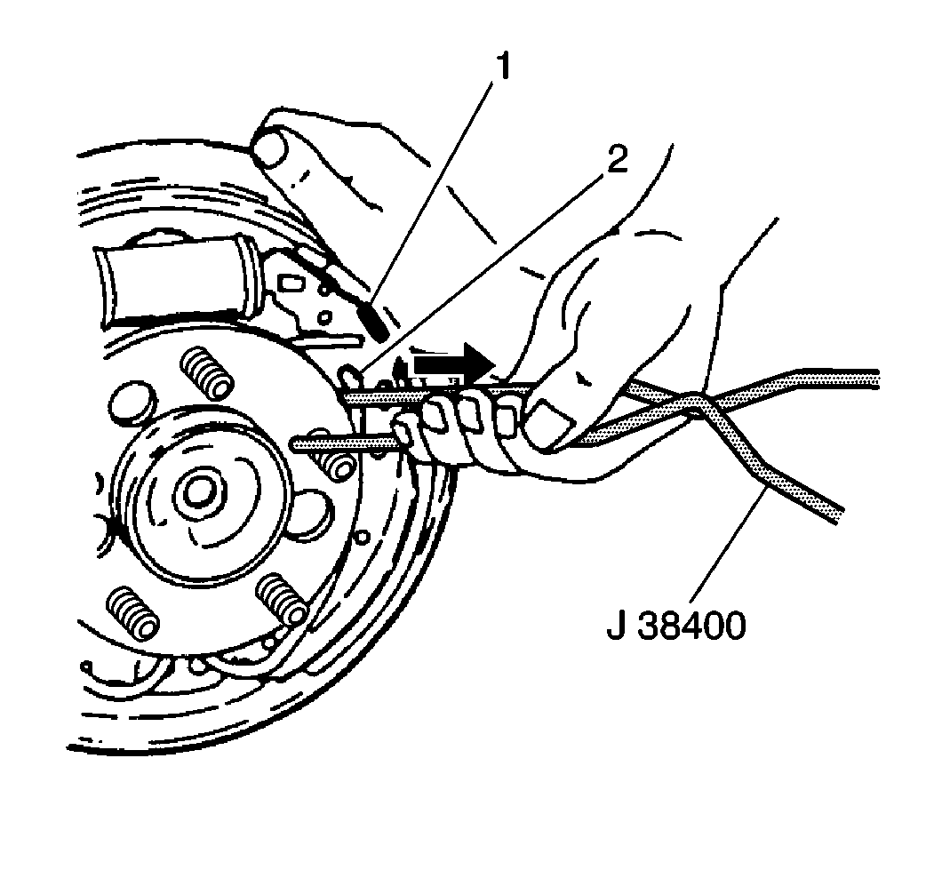
- Pry the end of the return
spring (2) toward the axle with the flat edge of the J 38400
until the return spring snaps down off
the shoe web onto the backing plate.
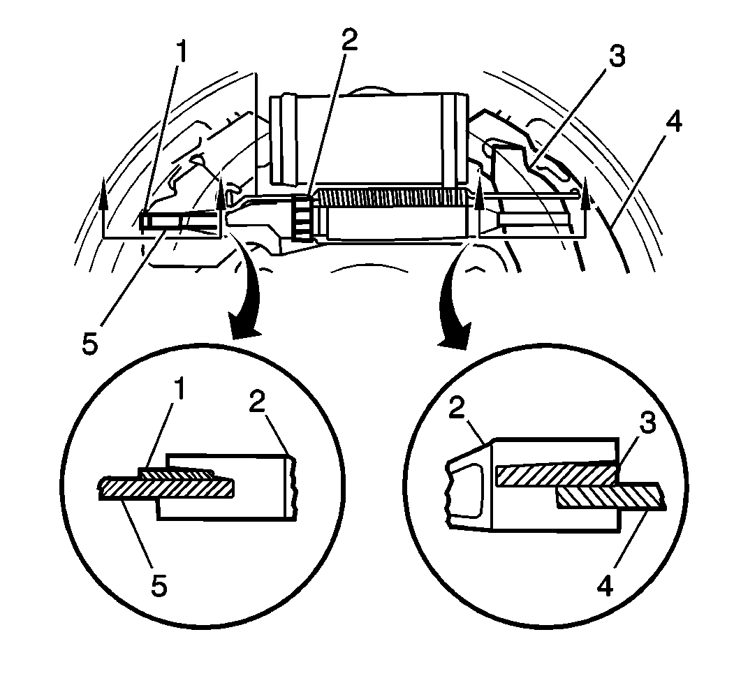
- Remove the adjuster actuator
(1) from the following components:
| • | The brake lining (4, 5) |
| • | The adjusting screw (2) |
- Remove the parking brake lever (3) from the parking brake shoe
. Do not remove the parking brake cable from the parking brake lever unless
the parking brake lever is to be replaced.

- Lift the end of the return
spring (2) from the parking brake shoe and the parking brake lining (1). Insert
the hook end of the J 38400
between the return spring and the parking brake shoe web. Pry or twist
the J 38400
in order
to lift the end of the spring out of the shoe web hole.

- Pry the end of the return
spring (2) toward the axle with the flat edge of the J 38400
until it snaps down off the shoe web
onto the backing plate.
- Remove the parking brake shoe.
- Remove the return spring from the backing plate. If only the shoes
and linings are being replaced, do not remove the return spring.
- Clean all parts in clean denatured alcohol.
- Inspect and replace any parts that are of doubtful strength or
quality due to the following conditions:
| • | Discoloration from heat |
- Inspect the wheel cylinder for the following conditions:
- Do not attempt to repair the wheel cylinder. Replace the wheel
cylinder, refer to
Wheel Cylinder Replacement
.
Installation Procedure
Important: Lubricate the following components with GM P/N 1052196 or equivalent
brake lubricant:
| • | The six raised shoe pads on the backing plate |
| • | The anchor surfaces on the backing plate. The anchor surfaces
contact the lower ends of the brake shoes. |

- Reinstall the hooking
center spring section under the tab on the anchor, if the return spring was
removed.
- Install the parking brake shoe and lining. Position the shoe on
the backing plate.
- Use the J 38400
in order to pull up the end of the return spring (2), resting the return
spring on the web of the brake shoe (1).
- Use the J 38400
in order to pull the end of the return spring over until the return
spring snaps in the slot in the brake shoe.

- Connect the parking brake
lever (3) to the parking brake shoe.
- Connect the parking brake cable to the parking brake lever, if
disconnected.
- Before reinstallation, disassemble, thoroughly clean and lubricate
the adjusting screw (2) in the following manner:
| • | Clean the adjuster screw threads with a wire brush. |
| • | Wash all components in clean denatured alcohol. |
| • | Apply GM P/N 1052196 or equivalent brake lubricant to the following
areas: |
| • | The adjuster screw threads |
| • | The inside diameter of the adjuster socket |
| • | Adequate lubrication is achieved when a continuous bead of lubricant
is on the end of the adjuster nut and the socket when the threads are fully
engaged |
- Inspect the threads of the adjuster screw for smooth rotation
over the full length.

- Install the following
components:
| • | The adjusting screw (2) |
| • | The adjuster shoe lining |
| • | Engage the adjuster nut end of the adjusting screw (2) with the
web of the parking brake shoe and the parking brake lever (3) |
| • | Position the adjuster shoe and lining so that the shoe web engages
the deep slot in the socket end of the adjusting screw |
- Install the return spring into the adjuster shoe and lining.
| 10.1. | Use the J 38400
in order to pull up the end of the return spring, resting the return
spring on the web of the brake shoe. |
| 10.2. | Use the J 38400
in order to pull the end of the return spring over until the return
spring snaps in the slot in the brake shoe. |
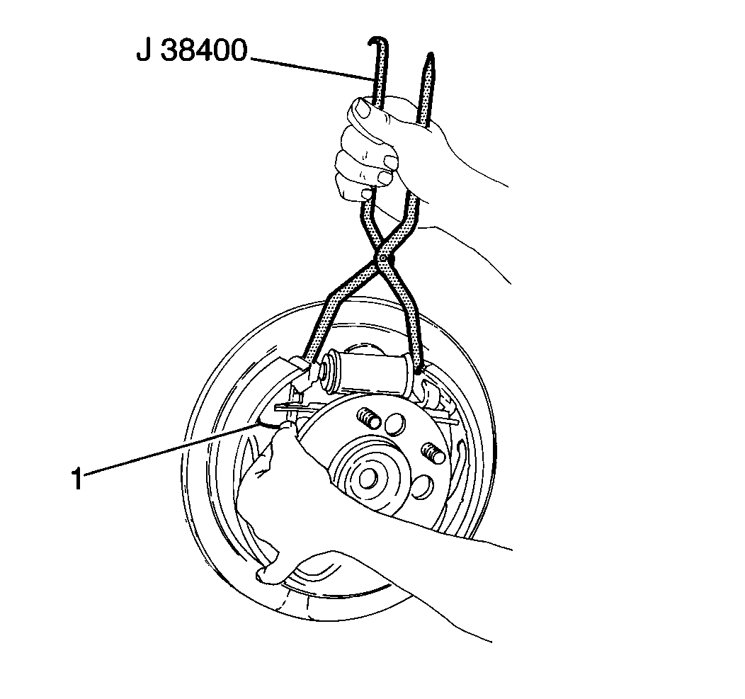
- Install the adjuster actuator.
| 11.1. | Lubricate the tab and the pivot point on the adjuster lever with
GM P/N 1052196 or equivalent brake lubricant. |
| 11.2. | Use the J 38400
in order to spread the brake shoes while working the adjuster actuator
(1) into position. |
- Install the adjuster spring.
| 12.1. | Engage the U-shaped end of the spring in the hole in the web
of the parking brake shoe. |
| 12.2. | Use the J 38400
in order to stretch the spring and engage the loop end over the tab
on the adjuster actuator. |

- Note the following items
in order to ensure the proper positioning and function of the adjuster actuator:
| • | The adjuster actuator pivots in the shoe web slot |
| • | The notch in the adjuster actuator rests on the step in the adjusting
screw (2) notch |
| • | The arm of the adjuster actuator rests freely on the star wheel
teeth of the adjuster screw, not trapped under the teeth in a downward angle |
| • | Use the J 38400
between the upper ends of the shoe and lining assemblies. Spread the
shoes apart and watch for proper rotation of the star wheel |
- Adjust the brakes. Refer to
Drum Brake Adjustment
.
- Install the brake drums. Align the marks made during removal.
- Install the tires and the wheels. Align the marks made during
removal. Refer to
Tire and Wheel Removal and Installation
in Tires and Wheels.
- Lower the vehicle.


