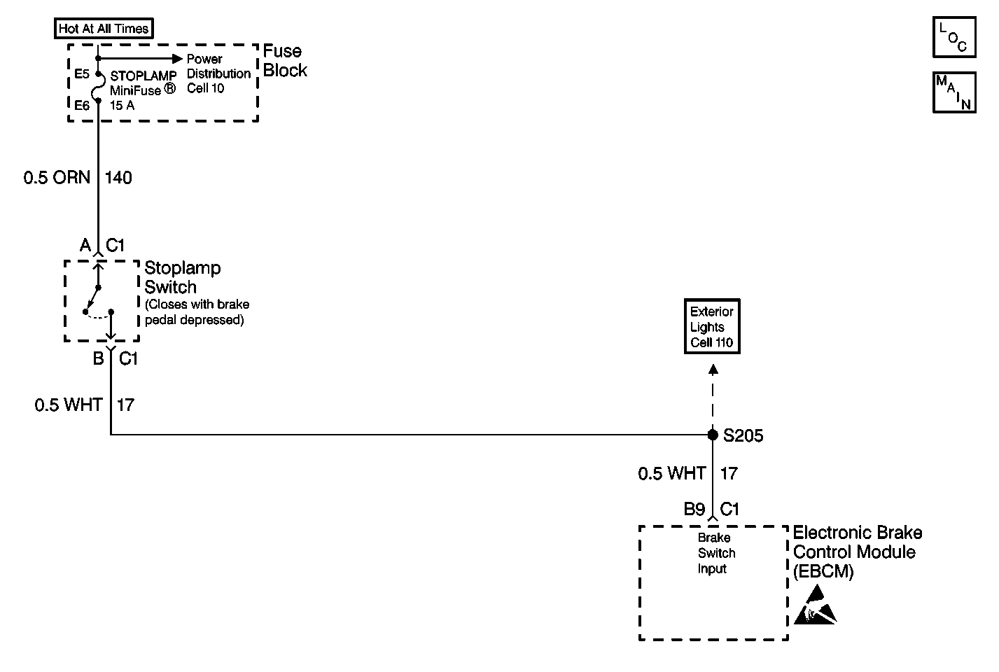
Circuit Description
DTC C1294 determines the proper operation of the brake switch. Proper operation of the brake switch is important because the brake switch is an input used to determine when an ABS event is needed. The brake switch deactivates the ABS when the brake switch is off.
Conditions for Setting the DTC
DTC C1294 can set if the vehicle's speed is greater than 40 km/h (25 mph).
A malfunction exists if the brake was always on during two consecutive drive cycles.
Action Taken When the DTC Sets
| • | A malfunction DTC stores. |
| • | ABS operation remains. |
Conditions for Clearing the DTC
| • | The condition responsible for setting the DTC no longer exists and the Scan Tool Clear DTCs function is used. |
| • | 100 drive cycles pass with no DTCs detected. |
Diagnostic Aids
The following conditions may cause an intermittent malfunction:
| • | A poor connection |
| • | Rubbed-through wire insulation |
| • | A broken wire inside the insulation |
| • | A misadjusated brake switch |
Use the enhanced diagnostic function of the Scan Tool in order to measure the frequency of the malfunction. Refer to the Scan Tool manual or Scan Tool Diagnostics located in this section for the procedure.
Thoroughly inspect any circuitry that may cause the intermittent complaint for the following conditions:
| • | Backed out terminals |
| • | Improper mating |
| • | Improperly formed or damaged terminals |
| • | Poor terminal-to-wiring connections |
| • | Physical damage to the wiring harness |
Step | Action | Value(s) | Yes | No | ||||||
|---|---|---|---|---|---|---|---|---|---|---|
1 | Was the Diagnostic System Check performed? | -- | ||||||||
2 |
Are the rear brake lamps on? | -- | ||||||||
3 | Disconnect the stoplamp switch connector C1. Are the rear brake lamps on? | -- | ||||||||
4 | Inspect the adjustment of the stoplamp switch. Is the stoplamp switch adjusted correctly? | -- | ||||||||
5 |
Do not start the engine. Is the voltage within the specified range? | 0-2 V | ||||||||
6 |
Is there evidence of poor terminal contact, terminal corrosion, or damaged terminals? | -- | ||||||||
7 |
Does DTC C1294 set as a current DTC during the last three drive cycles? | -- | ||||||||
8 | Repair the short to voltage in CKT 17. Is the repair complete? | -- | -- | |||||||
9 | Adjust the stoplamp switch. Refer to Stop Lamp Switch Adjustment in Brakes. Is the repair complete? | -- | -- | |||||||
10 | Replace the stoplamp switch. Refer to Stop Lamp Switch Replacement in Brakes. Is the repair complete? | -- | -- | |||||||
11 | Replace all of the terminals and connectors that exhibit the following conditions:
Is the repair complete? | -- | -- | |||||||
12 | Replace the EBCM. Refer to Electronic Brake Control Module Replacement . Is the repair complete? | -- | -- | |||||||
13 | Is the malfunction intermittent or is not present at this time? | -- | Go to Diagnostic Aids | -- |
