Ignition Switch Assembly - Assemble - Off Vehicle Column Shift
Assembly Procedure
- Turn the steering column lock cylinder set to the "off-lock" position.
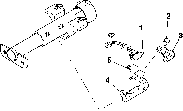
- Install the stud and bracket assembly (4) onto the steering column jacket assembly.
- Install the TORX® washer head screw (5).
- Install the park position switch assembly (1) onto the stud and bracket assembly (4).
- Install the park position head screw.
- Install the cable shift cam assembly (3) onto the stud and bracket assembly (4).
- Install the cam retainer (2) into the cable shift cam assembly (3).
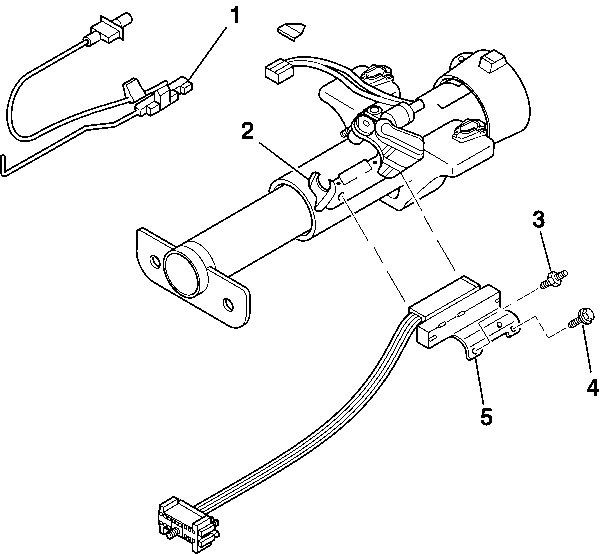
- Install the ignition switch assembly (5) onto the stud and bracket assembly.
- Adjust the ignition switch assembly (5) following these steps:
- Install the ignition switch actuator assembly (1) to the ignition switch assembly (5).
- Install the dimmer switch mounting stud (3) to the ignition switch assembly (5).
- Install the TORX® washer head screw (4).
- Remove the drill bit from the ignition switch assembly.
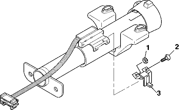
- Install the PRNDL adjuster assembly (3) to the dimmer switch mounting stud.
- Install the hexagon washer head screw (2).
- Install the hexagon nut (1).
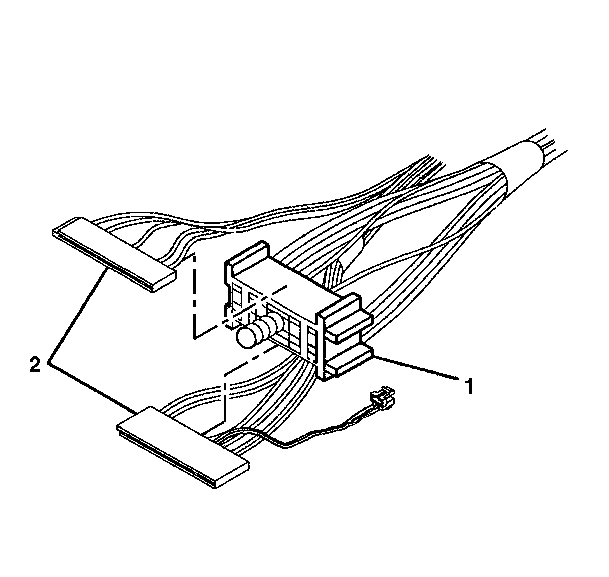
- Install the pivot and pulse dimmer switch assembly connector (2) to the bulkhead connector (1).
- Install the turn signal switch assembly connector (2) to the bulkhead connector (1).
- Connect the park position switch assembly connector to the interlock solenoid assembly.
Important: The BTSI cable assembly must remain straight during assembly.

Notice: Use the correct fastener in the correct location. Replacement fasteners must be the correct part number for that application. Fasteners requiring replacement or fasteners requiring the use of thread locking compound or sealant are identified in the service procedure. Do not use paints, lubricants, or corrosion inhibitors on fasteners or fastener joint surfaces unless specified. These coatings affect fastener torque and joint clamping force and may damage the fastener. Use the correct tightening sequence and specifications when installing fasteners in order to avoid damage to parts and systems.
Tighten
Tighten the TORX® washer head screw (5) to 4 N·m
(35 lb in).
Tighten
Tighten the park position head screw to 2.5 N·m (22 lb in).
Tighten
Tighten the cam retainer (2) to 4 N·m (35 lb in).

| 9.1. | Move the switch slider to the extreme right position. |
| 9.2. | Move the switch slider one detent to the left "off-lock" position. |
| 9.3. | Install 3/32 inch drill bit in the hole on the switch to limit travel. |
Tighten
Tighten the dimmer switch mounting stud (3) to 4 N·m
(35 lb in.)
Tighten
Tighten the TORX® washer head screw (4) to 4 N·m
(35 lb in).

Tighten
Tighten the hexagon washer head screw (2) to 4 N·m
(35 lb in).
Tighten
Tighten the hexagon nut (1) to 4 N·m (35 lb in).

