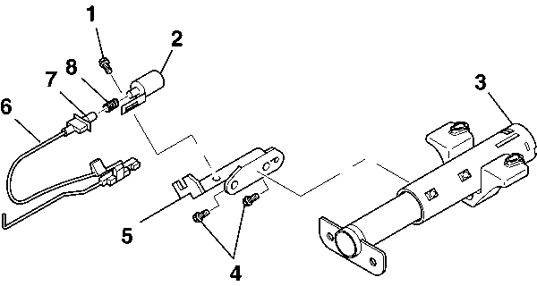
- Install the solenoid adapter bracket (5)
onto the steering column jacket assembly.
Important: The BTSI cable assembly (6) must remain straight during assembly.
Notice: Use the correct fastener in the correct location. Replacement fasteners
must be the correct part number for that application. Fasteners requiring
replacement or fasteners requiring the use of thread locking compound or sealant
are identified in the service procedure. Do not use paints, lubricants, or
corrosion inhibitors on fasteners or fastener joint surfaces unless specified.
These coatings affect fastener torque and joint clamping force and may damage
the fastener. Use the correct tightening sequence and specifications when
installing fasteners in order to avoid damage to parts and systems.
- Install the 2 hexagon washer head
screws (4) to the solenoid adapter bracket (5).
Tighten
Tighten the hexagon washer head screws (4) to 4 N·m
(35 lb in).
- Install the interlock solenoid assembly (2) to the solenoid
adapter bracket (5).
- Install the hexagon washer head screw (1) to the interlock
solenoid assembly (2).
Tighten
Tighten the hexagon washer head screw (1) to 4 N·m
(35 lb in).
- Install the BTSI cable assembly (6) to the ignition switch
actuator assembly.
- Disengage the locking button on the BTSI cable assembly (6)
to allow cable movement during adjustment.
- Clip the BTSI cable assembly (6) to the solenoid adapter
bracket (5).
- Install the ball joint spring (8) to the interlock solenoid
assembly (2).
- Install the ball joint socket to the interlock solenoid assembly (2).
- Adjust the interlock solenoid assembly (2) following these
steps:
Important: The interlock solenoid assembly (2) will become hot while adjusting.
| 10.1. | Put the steering column lock cylinder set into the "RUN"
position. |
| 10.2. | Take the shift lever out of the "PARK" position. |
| 10.3. | Pull the BTSI cable assembly (6) away from the interlock
solenoid assembly (2). |
| 10.4. | The BTSI cable assembly (6) fitting will start to extend. |
| 10.5. | This compresses the ball joint spring (8) inside the ball
joint socket. |
| 10.6. | Do not extend the BTSI cable assembly (6) fitting any further
at this point. |
| 10.7. | Let the BTSI cable assembly (6) move back 1 to 2 mm. |
| 10.8. | Engage the locking button on the BTSI cable assembly (6). |
- Inspect the interlock solenoid assembly (2) following these
steps:
Important: The interlock solenoid assembly (2) will become hot while adjusting.
| 11.1. | The interlock solenoid assembly (2) must lock the gear
shift lever bowl assembly when the steering column is in the "PARK"
position. |
| 11.2. | The interlock solenoid assembly (2) must lock the gear
shift lever bowl assembly when shifting to "PARK" without pressing
the brake pedal. |
| 11.3. | The interlock solenoid assembly (2) must release the gear
shift lever bowl assembly when pressure is applied to the brake pedal. |
| 11.4. | Readjust if needed. |

