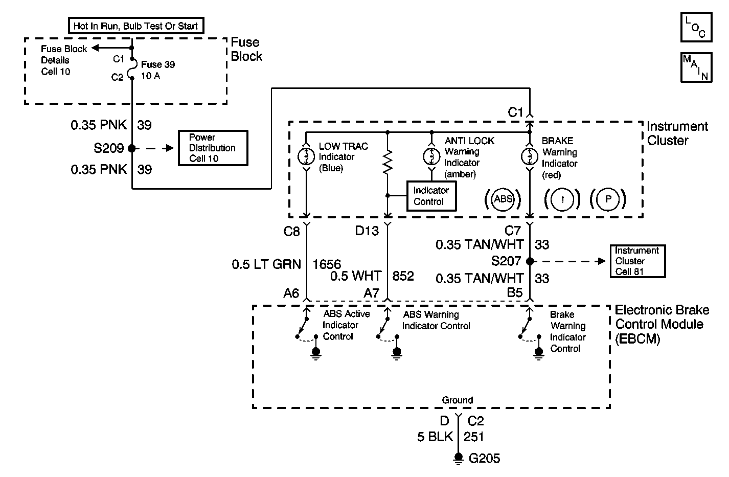
For 1990-2009 cars only

Circuit Description
The LOW TRAC Indicator is controlled by the EBCM. The LOW TRAC Indicator is activated during a traction control event only. When the EBCM detects a low traction condition it supplies a ground for CKT 1656 turning on the LOW TRAC Indicator.
Diagnostic Aids
| • | It is very important that a thorough inspection of the wiring and connectors be performed. Failure to carefully and fully inspect wiring and connectors may result in misdiagnosis, causing part replacement with reappearance of the malfunction. |
| • | Thoroughly inspect any circuitry that may be causing the complaint for the following conditions: |
| - | Backed out terminals |
| - | Improper mating |
| - | Improperly formed or damaged terminals |
| - | Poor terminal-to-wiring connections |
| - | Physical damage to the wiring harness |
| • | The following conditions may cause an intermittent malfunction: |
| - | A poor connection |
| - | Rubbed-through wire insulation |
| - | Dirty or corroded terminals |
| - | A broken wire inside the insulation |
| • | If an intermittent malfunction exists refer to General Electrical Diagnosis in Wiring Systems for further diagnosis. |
| • | Zero the J 39200 test leads before making any resistance measurements. |
Step | Action | Value(s) | Yes | No |
|---|---|---|---|---|
1 | Was the Diagnostic System Check performed? | -- | ||
2 |
Did the amber ABS indicator LOW TRAC turn on? | -- | ||
3 |
Does the Amber Low Trac indicator come on? | -- | ||
4 |
Is the resistance within the range specified in the values column? | 0.2-10 ohms | ||
5 | Repair a short to voltage in CKT 1656. Is the repair complete? | -- | -- | |
6 |
Did the LOW TRAC Indicator comes on for approximate 3 seconds then turn OFF? | -- | SYSTEM OK | |
7 | Replace the EBCM. Refer to Electronic Brake Control Module Replacement . Is the repair complete? | -- | -- |
