For 1990-2009 cars only
Tools Required
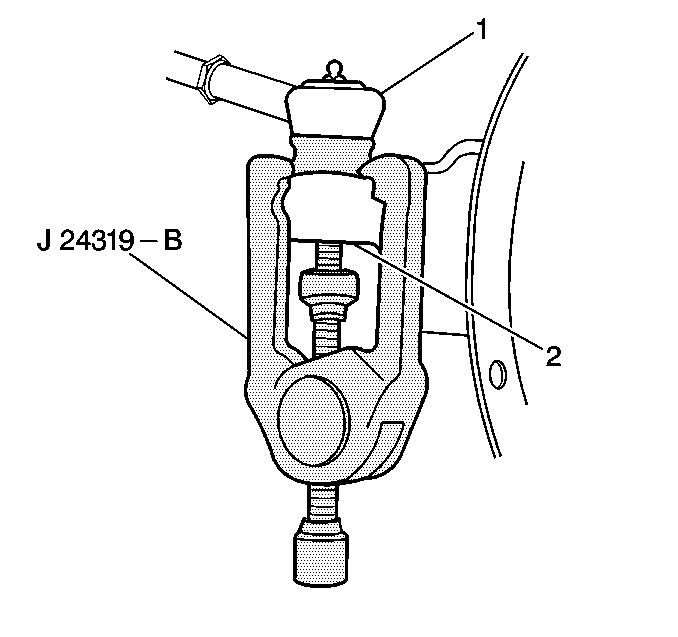
J 24319-B Universal Steering Linkage Puller
Removal Procedure
- Raise and support the vehicle. Refer to Lifting and Jacking the Vehicle in General Information.
- Remove the tire and wheel assembly. Refer to Tire and Wheel Removal and Installation in Tires and Wheels.
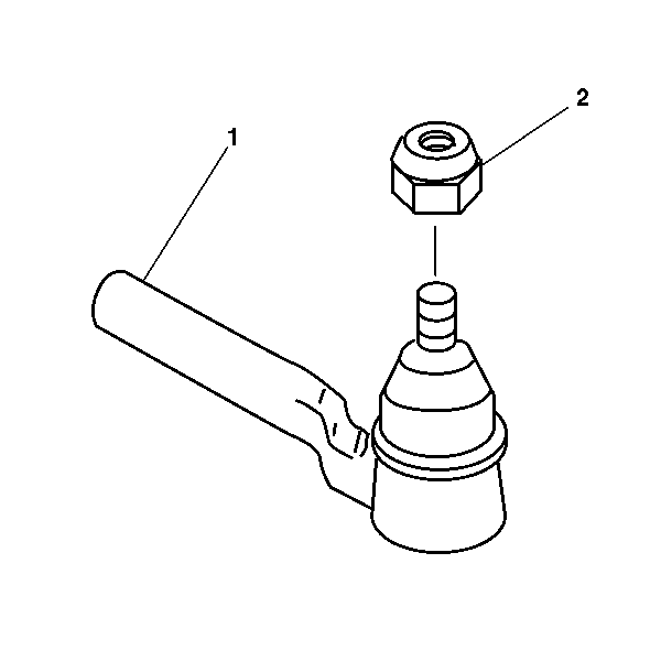
- Remove the prevailing torque nut (2) from the outer tie rod assembly (1).
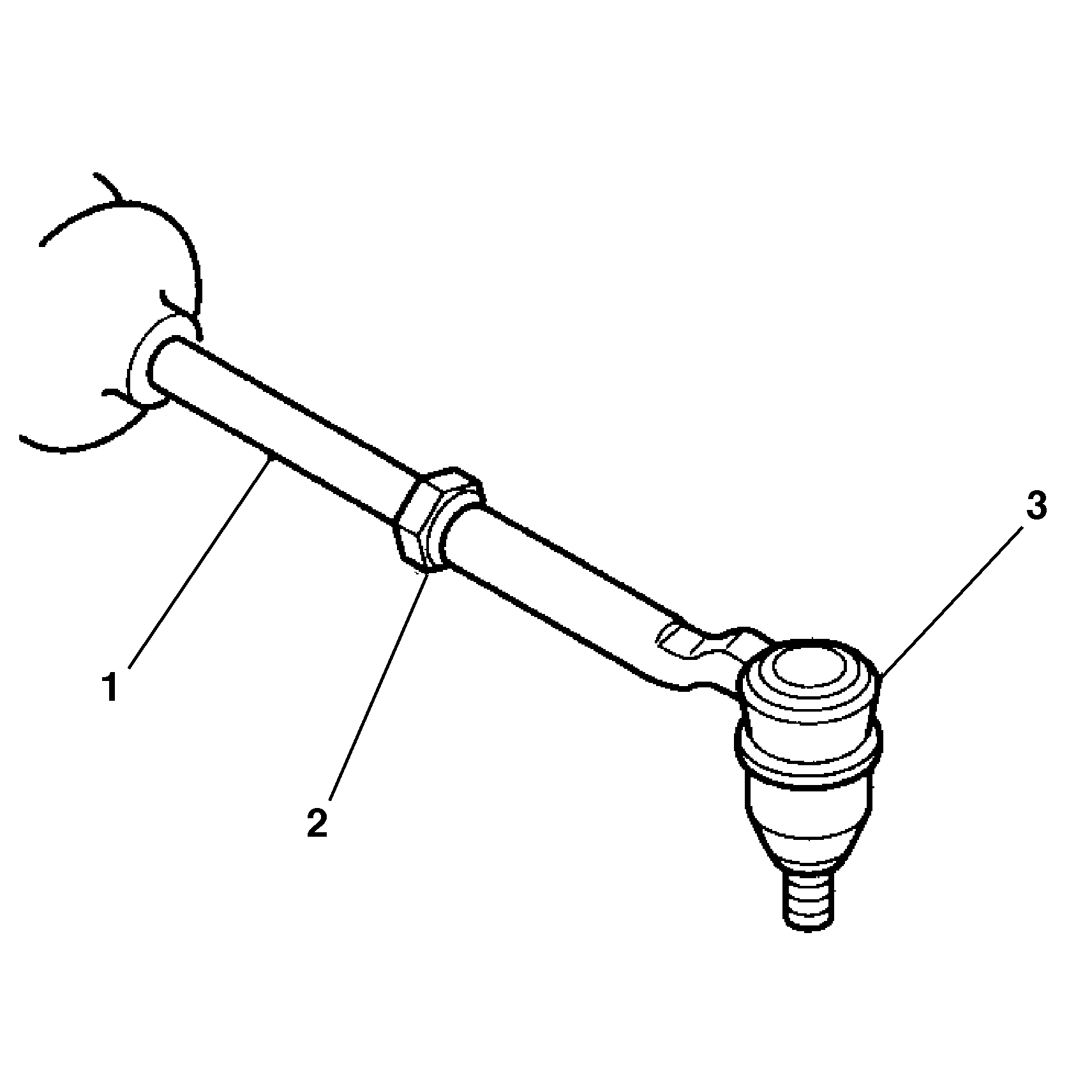
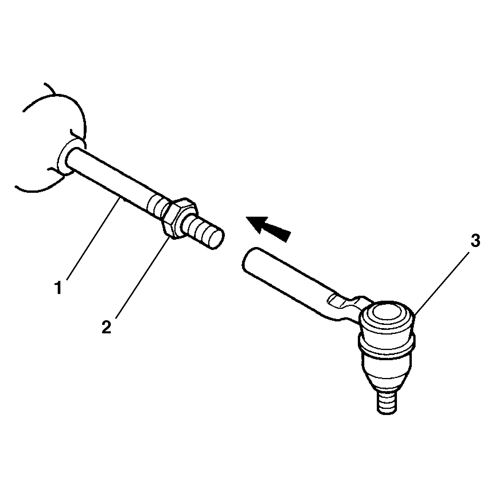
- Loosen the jam nut (2) on the inner tie rod assembly (1).
- Using theJ 24319-B remove the outer tie rod assembly (2) from the steering knuckle (1).
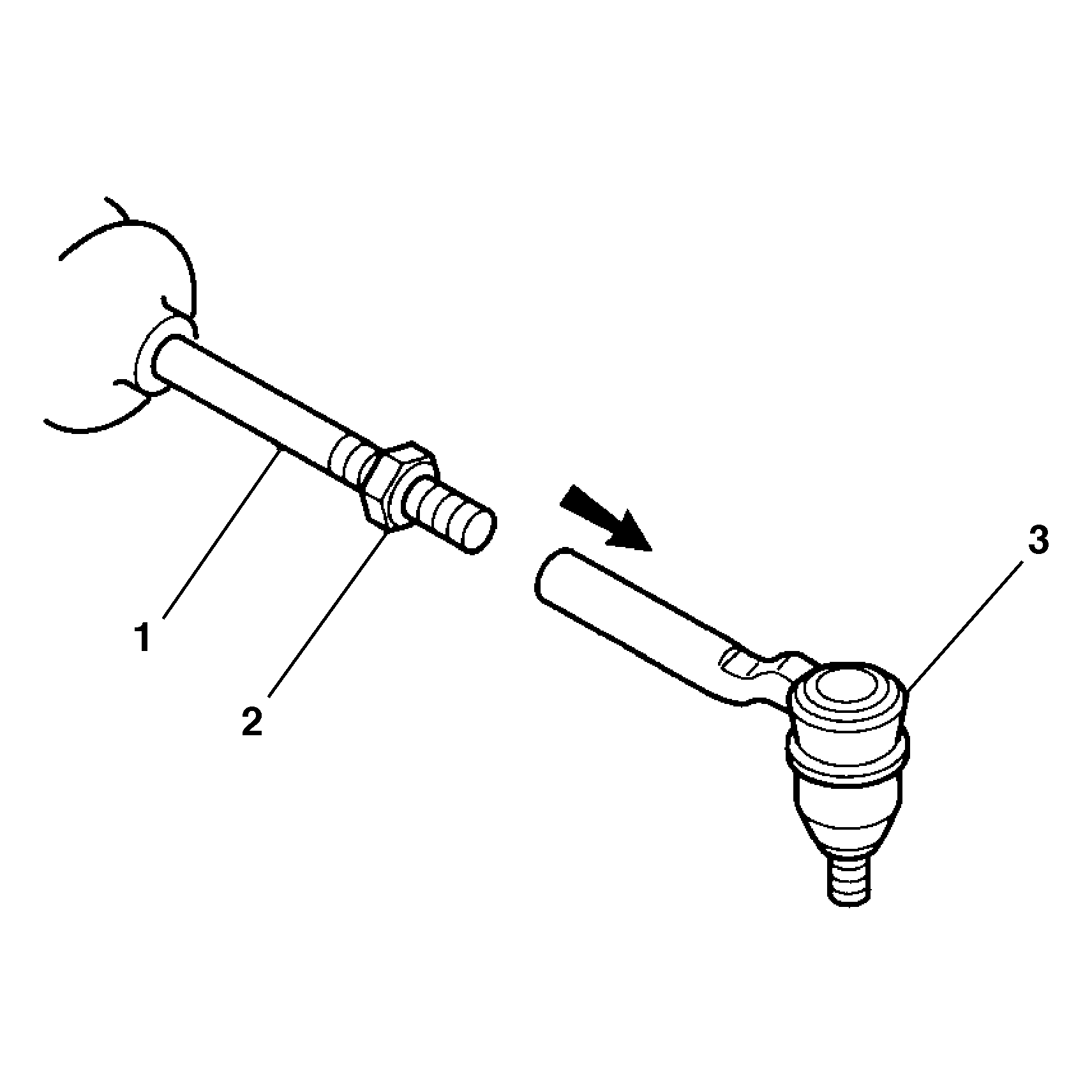
- Remove the outer tie rod assembly (3) from the inner tie rod assembly (1).
Installation Procedure
- Install the outer tie rod assembly (3) to the inner tie rod assembly (1).
- Do not tighten the jam nut (2).
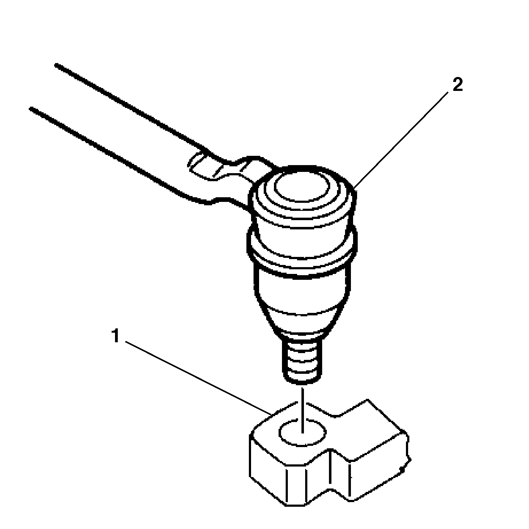
- Install the outer tie rod assembly (2) to the steering knuckle (1).
- Install the prevailing nut (2) to the outer tie rod assembly (1).
- Tighten the jam nut (2) against the outer tie rod assembly (3).
- Install the tire and wheel assembly. Refer to Tire and Wheel Removal and Installation in Tires and Wheels.
- Lower the vehicle.
- Perform a front end alignment. Refer to Preliminary Alignment Inspection in Wheel Alignment.

Tighten
Tighten the prevailing torque nut (2) to 30 N·m
(22 lb ft).Tighten the prevailing torque nut (2) an additional
120 degrees of rotation.

Tighten
Tighten the jam nut to 68 N·m (50 lb ft).
