IGN. NOISE IN SPEAKERS (REROUTE WIRE & RELOCATE FUSE)

Subject: IGNITION NOISE IN SPEAKERS
Model and Year: 1992 APV WITH 3800 ENGINE (RPO L27)
Application: 1992 "U" Van with 3800 Engine (VIN Code L) (RPO L27) only.
Condition:
---------- Ignition noise may be heard in the speakers while playing a cassette, or may be heard in the right front speaker in any radio mode.
Cause:
------ The ignition feed wire for the Direct Ignition System (DIS) is routed close to the radio receiver. This ignition wire emits a pulsating magnetic field from the DIS module that may be picked up by the tape head and amplified to the speakers. The right front speaker wire may also pick up this field in any radio mode.
Correction:
----------- To correct this condition, reroute the ignition power feed wire away from the radio, and relocate the fuse to an in-line fuse connector under the steering column, using the following procedure.
NOTICE: The integrity of the battery power feed circuit for the ignition system is critical for engine operation. Proper procedures for the splicing of copper wires, as defined in Section 8A of the Service Manual, must be closely followed while performing this procedure. All splices should be crimped, soldered, and taped to insure a good connection.
1. Disconnect the negative battery cable.
2. Obtain the jumper wire kit, P/N 12141459.
3. Remove the left hand lower sound insulator panel and the lower trim cover. Remove the gear selector indicator wire from the steering column.
4. Remove the right hand sound insulator panel and the glove box.
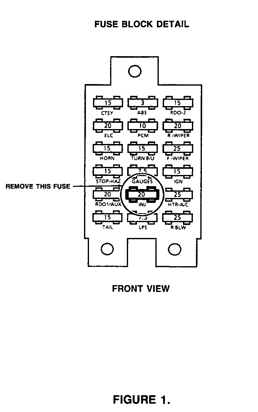
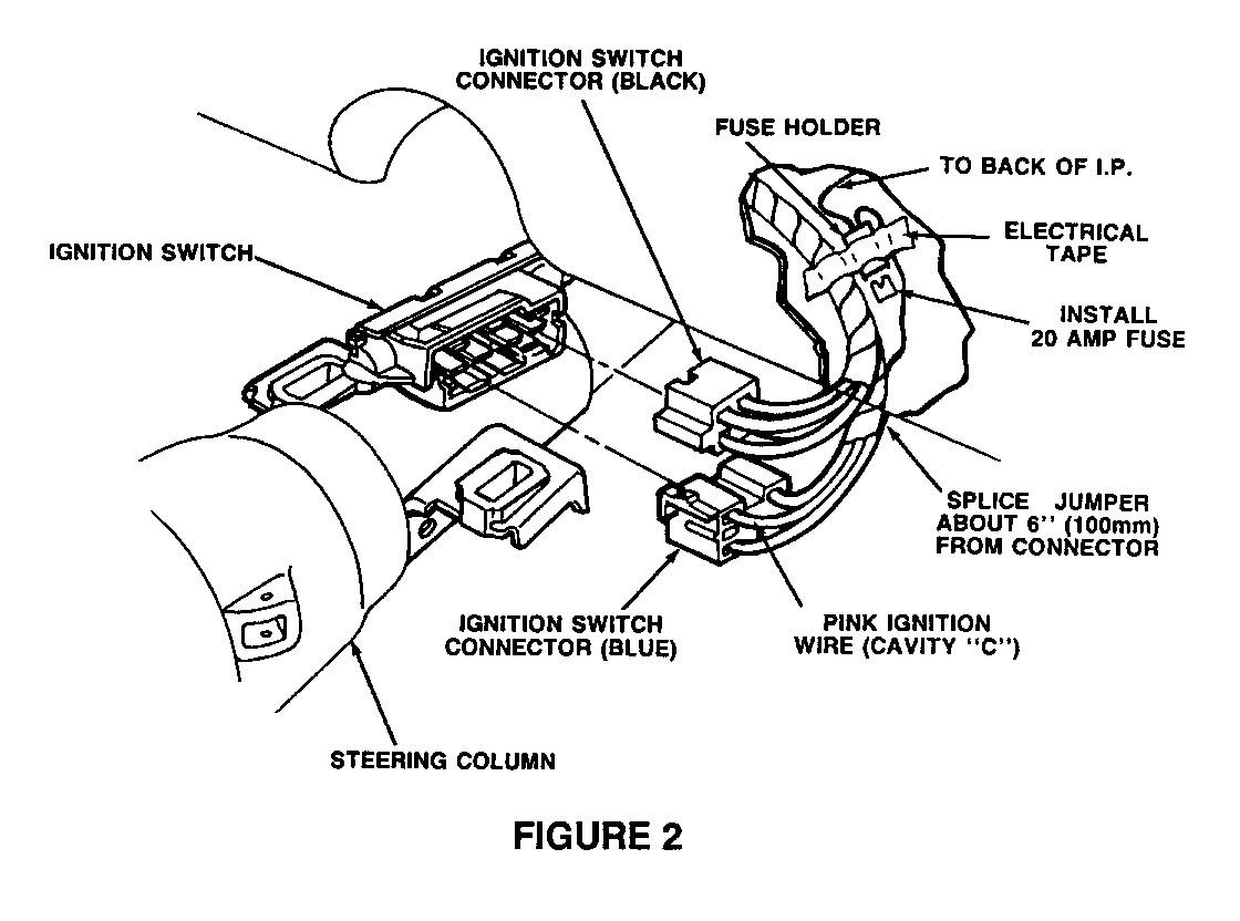
5. Remove the 20 amp "INJ" fuse from the fuse block (see Figure 1) and install into the jumper harness fuse holder (see Figure 2).
6. Lower the steering column to gain access to the ignition switch wiring (as shown in Figure 2). Disconnect the black connector, and then the blue connector from the ignition switch.
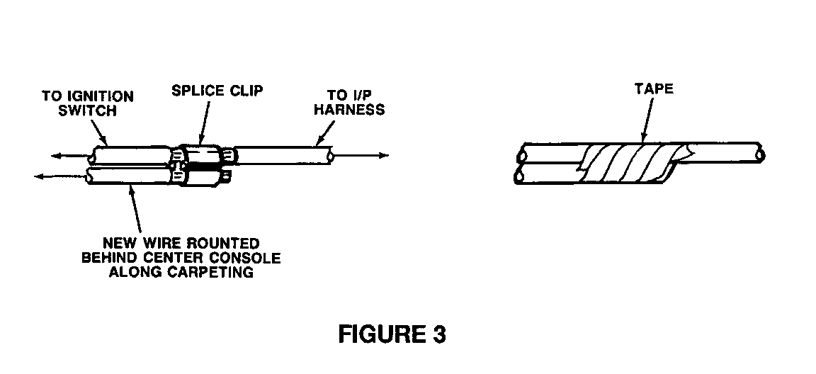
7. Splice, solder, and tape the short pink wire from the jumper harness into the pink wire (#3 circuit) in cavity "C" of the blue connector about 6 inches behind the connector, as shown in Figure 2. You may have to remove some tape from the harness.
DO NOT CUT THE EXISTING WIRE. SPLICE ONTO IT ONLY. DO NOT USE "QUICK CONNECT" TYPE SPLICE CLIPS. See Figure 3 for details.
8. Lay the fuse holder next to the harness and tape the holder onto the harness. Do not tape over the fuse. Be sure the fuse is visible when the trim is removed, to allow for future service. Connect the blue and black connectors to the ignition switch.
9. Reinstall the steering column, and install and adjust the wire to the gear indicator.
10. Route the pink/black wire as far forward in the IP as possible. Tape the wire to the HVAC vacuum lines on the left side. Route the wire forward to the carpet and behind the HVAC ducts, toward the right side of the vehicle. Make sure that the wires are secured away from any moving parts, such as the accelerator linkage.
11. Reinstall the left hand sound insulator panel and trim cover.
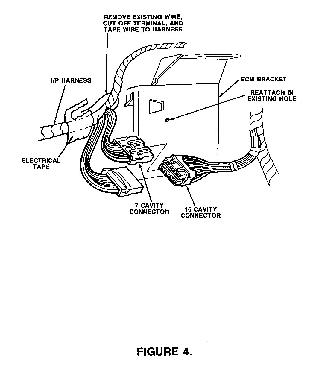
12. Locate the 15 cavity connector clipped to the back of the ECM bracket and loosen from clip (see Figure 4). Disconnect the 7 cavity connector and remove the pink/black wire from cavity "M". Cut the terminal off, fold the wire back, and tape to the harness.
13. Insert the terminal from the jumper harness into cavity "M". Plug the connector back into the 15 cavity connector, and clip the connector to the ECM bracket.
14. Tape any excess wire from the jumper harness as far forward in the vehicle as possible, keeping it far away from the radio receiver.
15. Reinstall the glove box, and right hand sound insulator panel.
16. Reconnect the negative battery cable.
Parts are expected to be available on 11/30/92. In case of limited inventory, parts will be placed on 400 control to waive VIP surcharges. Only verifiable emergency VIP orders will be accepted. SPO will make every effort to obtain parts. However, the part will be shipped premium transportation at dealer's expense and all other order types will be placed on backorder until the 400 control is removed.
Warranty Information:
Labor Operation: Tl897
Labor Time: 0.9 Hr.


General Motors bulletins are intended for use by professional technicians, not a "do-it-yourselfer". They are written to inform those technicians of conditions that may occur on some vehicles, or to provide information that could assist in the proper service of a vehicle. Properly trained technicians have the equipment, tools, safety instructions and know-how to do a job properly and safely. If a condition is described, do not assume that the bulletin applies to your vehicle, or that your vehicle will have that condition. See a General Motors dealer servicing your brand of General Motors vehicle for information on whether your vehicle may benefit from the information.
