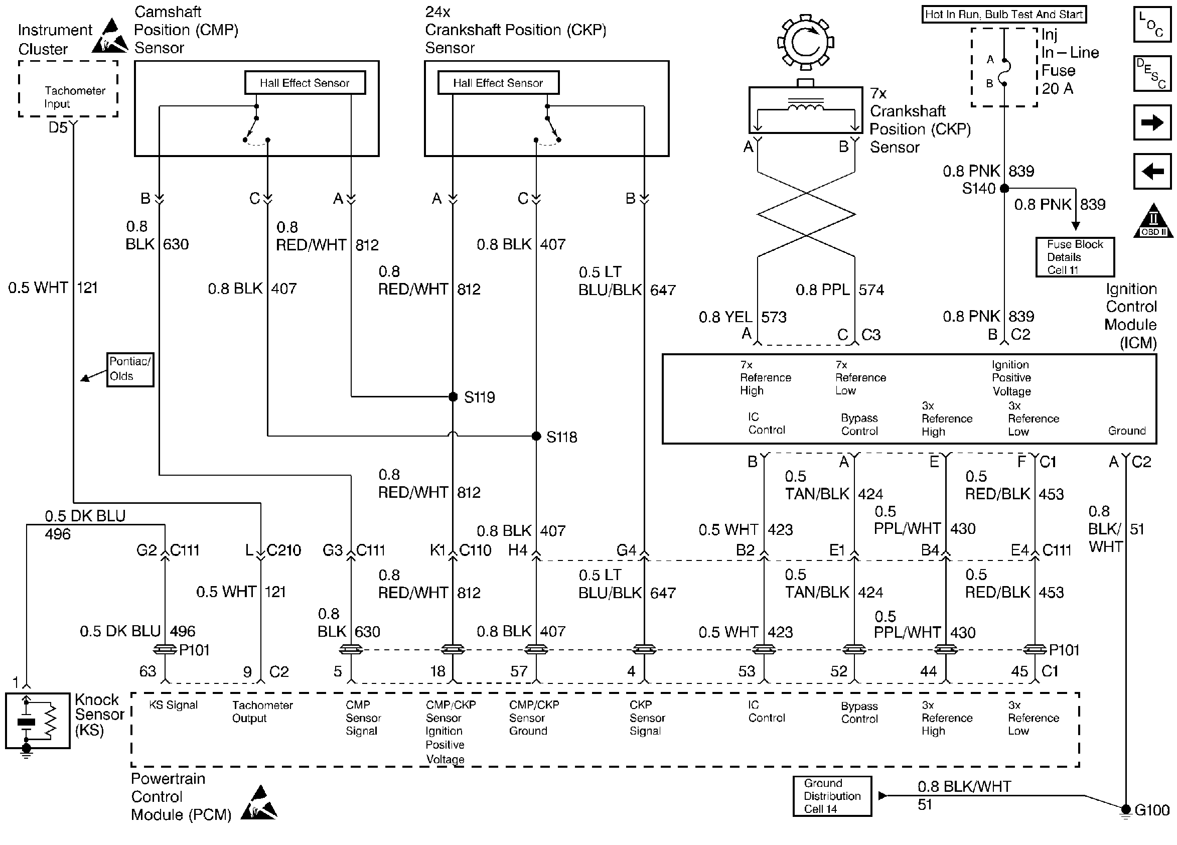
Refer to
Ignition System

.
Circuit Description
During cranking, the Ignition Control Module (ICM) monitors the 7X crankshaft position sensor signal. Once the ICM determines spark synchronization, 3X reference signals are sent to the PCM. The PCM will command all six injectors ON for one priming shot of fuel in all cylinders. After the priming, the injectors are left OFF for the next six fuel control reference signals (two crankshaft revolutions). This allow each cylinder a chance to use the fuel from the priming shot. During this waiting period, a cam pulse will have been received by the PCM. The PCM uses the Cam signal pulses to initiate sequential fuel injection. The PCM constantly monitors the number of pulses on the Cam signal circuit and compares the number of Cam pulses to the number of 24X reference pulses and the number of 3 X reference pulses being received. If the PCM receives an incorrect number of pulses on the Cam reference circuit, DTC P0341 will set and the PCM will initiate injector sequence without the Cam signal with a one in six chance that injector sequence is correct. The engine will continue to start and run normally, although the misfire diagnostic will be affected if a misfiring condition occurs.
Conditions for Setting the DTC
| • | The engine is running (3X reference pulses are being received). |
| • | The ratio of 3X reference pulses to Cam pulses received by the PCM does not equal 6. |
| • | The ratio of 24X reference pulses to 3X reference pulses received by the PCM equals 8. |
| • | Above conditions for 30 seconds. |
Action Taken When the DTC Sets
| • | The PCM will illuminate the MIL during the second key cycle in which the DTC sets. |
| • | The PCM will initiate injector sequence without the Cam signal with a one in six chance that injector sequence is correct. |
| • | The PCM will store conditions which were present when the DTC set as Freeze Frame and Fail Records data. |
Conditions for Clearing the MIL/DTC
| • | The PCM will turn the MIL OFF on the third consecutive trip cycle during which the diagnostic has been run and the fault condition is no longer present. |
| • | A history DTC P0341 will clear after 40 consecutive warm-up cycles have occurred without a fault. |
| • | DTC P0341 can be cleared by using the scan tool Clear Info function or by disconnecting the PCM battery feed. |
Diagnostic Aids
DTC P0341 can be caused by secondary components leaking high voltage into the ignition module. Check for the following conditions:
| • | Incorrect harness routing near secondary ignition components; |
| • | Ignition coil arcing to wiring harness or Ignition Control Module (check ignition coils for cracks, carbon tracking, or other signs of damage); |
| • | Secondary ignition wire(s) arcing to wiring harness. |
An intermittent may be caused by a poor connection, rubbed through wire insulation or a wire broken inside the insulation. Check for:
| • | Faulty Ignition Coil. Inspect the ignition coils for cracks, carbon tracking, or other signs that indicate that the coil secondary circuit is arcing to the ICM or ICM wiring harness. |
| • | Poor connection. Inspect the PCM harness and connectors for improper mating, broken locks, improperly formed or damaged terminals, and poor terminal to wire connection. |
| • | Damaged harness. Inspect the wiring harness for damage. If the harness appears to be OK, disconnect the PCM, turn the ignition ON and observe a voltmeter connected to the CAM signal circuit at the PCM harness connector while moving connectors and wiring harnesses related to the 24X Crankshaft Position Sensor and Camshaft Position Sensor. The Camshaft Position and 24X sensors share the same sensor feed from the PCM. A change in voltage will indicate the location of the fault. |
Reviewing the Fail Records vehicle mileage since the diagnostic test last failed may help determine how often the condition that caused the DTC to be set occurs. This may assist in diagnosing the condition.
Test Description
Number(s) below refer to the step number(s) on the Diagnostic Chart.
-
Checks that the fault is present.
-
This vehicle is equipped with a PCM which utilizes an Electrically Erasable Programmable Read Only Memory (EEPROM). When the PCM is being replaced, the new PCM must be programmed.
Step | Action | Value(s) | Yes | No | ||||||||
|---|---|---|---|---|---|---|---|---|---|---|---|---|
1 | Was the Powertrain On-Board Diagnostic (OBD) System Check performed? | -- | ||||||||||
Note test result; does scan tool indicate DTC P0341 failed this ign? | -- | Refer to Diagnostic Aids | ||||||||||
3 |
Does the DVM display a voltage near the specified value? | B+ | ||||||||||
4 |
Does the DVM display a voltage near the specified value? | B+ | ||||||||||
5 |
Was a problem found? | -- | ||||||||||
6 |
Was a problem found? | -- | ||||||||||
7 | Check connections at the PCM and replace terminals if necessary. Refer to repair Procedures in Electrical Diagnosis. Did any terminals require replacement? | -- | ||||||||||
8 | Replace the CMP sensor. Refer to Camshaft Position Sensor Replacement . Is action complete? | -- | -- | |||||||||
Replace the PCM. Important: Replacement PCM must be programmed. Refer to Powertrain Control Module Replacement/Programming . Is action complete? | -- | -- | ||||||||||
10 |
Does the scan tool indicated DTC P0341 failed this ign? | -- | System OK |
