DTC P2138 Accel Pedal Position Sensor (Export Only)

| Subject: | DTC P2138 Accel Pedal Position Sensor |
| Models: | 2007-2008 Chevrolet Caprice, Lumina (Export Only) |
Condition
Technicians may find a DTC P2138 (Accelerator Pedal Position Sensor 1-2 Correlation) set in the ECU. The vehicle will default to "safety mode" and the Check Engine Light will illuminate.
Cause
Fretting corrosion on the engine harness terminals at the X102 or X104 connectors on V6 engines and the X104 connector only on V8 engines is the most likely cause for setting the ECU code P2138.
Logging of this DTC is NOT the result of either the pedal or the ECU in each incident reported to date.
Fretting corrosion of the terminal contact surfaces causes degeneration in electrical contacts, resulting in a resistance at the connector terminals. This can create an inaccurate voltage reading at the pedal sensors. P2138 code will set as the ECU incorrectly receives a variation in signal from Accelerator Pedal Position Sensor 1 and 2.
Vibrations and temperature from customer drive cycles can cause fretting corrosion on the terminals of these connectors.
Correction
After verifying that P2138 is set, perform the following procedure.
Do not replace the ECU or the pedal for this condition.
- Disconnect both harness connectors X102 and X104. Test harness integrity between the ECU and the pedal and check the harness for rub through. Repair if required.
- Inspect the connector condition and retention of connectors and terminals. Repair as required. Look for terminals that have been damaged, not fully seated in connector, backed out, etc.
- Using an appropriate sized tool, such as another male terminal or emery paper, physically scrape the surface of the male and female terminals as thoroughly as possible. Note - it will be necessary to remove the terminal from the housing to perform this work.
- After scraping the terminals, clean inside the connectors and terminals using a terminal cleaning spray to ensure no visible foreign material (dust, lint, etc.) is present.
- Ensure terminal contact is good by inserting an appropriate sized terminal* into the female terminal. Tighten the female terminal if required. (* As found in GM Electronic kit KM-609, available from SPX.)
- Apply grease (P/N 92146329) to the sockets/terminals of the connector and reconnect. Perform a disconnect/reconnect at least three times to ensure the grease is worked into the female side of the terminal/connector. It is important to ensure the grease has adequately penetrated the terminals prior to retesting to ensure sufficient contact can be re-established between terminals after fretting corrosion has occurred.
- Clear all DTCs as per the normal process.
Important: Failure to scrape these terminals will result in a repeat failure as the corrosion will not be removed by just using a terminal cleaning spray.
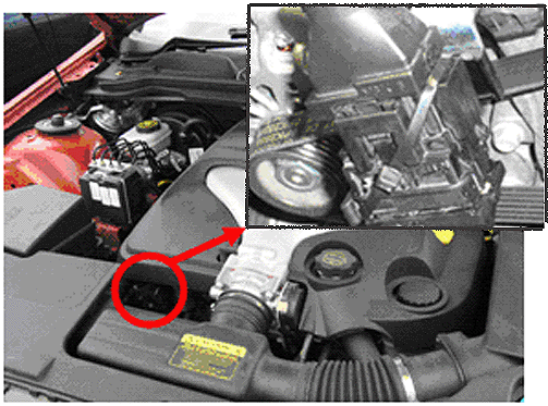
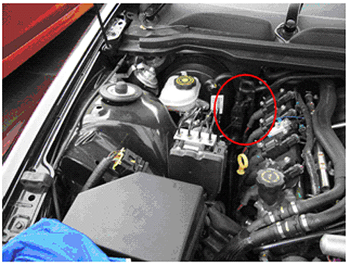
Important: Attach a tie strap (P/N 92058858) on a diagonal across the connector (refer to photos below) to prevent unnecessary movement at the connector.
V6 Connector Location and Tie Strap Attachment Method

V8 Connector Location - Attach Tie Strap in Same Manner as shown in V6 Photo above

Parts Information
Part Number | Description | Qty |
|---|---|---|
92146329 | Terminal Lube Grease | 1 |
92058858 | Tie Strap | 1 |
Warranty Information
Labor Operation | Description | Labor Time |
|---|---|---|
N6608 | P2138 Connector Secure | 0.3 hr |
