Tools Required
| • |
| • |
| • |
| • |
| • |
| • |
| • |
| • |
- Measure the thickness of DT-48806 (1) using a depth gauge (2).(e.g - 3.67mm).
- Record the thickness of the DT-48806 (1).
- Measure the thickness of the DT-48806 (1) and the pinion head bearing (2) with the depth gauge (3) (e.g - 33.925mm).
- Record the thickness of the DT-48806 (1) and pinion head bearing (2).
- Subtract the thickness of DT-48806 (1) 3.67mm from the total thickness of the pinion bearing measurement spacer (1) and the pinion bearing (2) 33.925mm to determine the pinion head bearing (2) thickness.
- Example - The pinion head bearing (2) thickness is 33.925mm - 3.67mm = 30.255mm
- Record the serial number (1), set number (3) and size (4) which are stamped into the pinion gear (2).
- Example:
- Check that the serial number (1) and set number (3) which are stamped into the ring gear (2) match those of the pinion set in step 7.
- Example:
- Identify the differential housing.
- Record the differential housing size. Example - 138.180mm
- Determine the thickness of the pinion shim.
- Position the correct shim onto the pinion head.
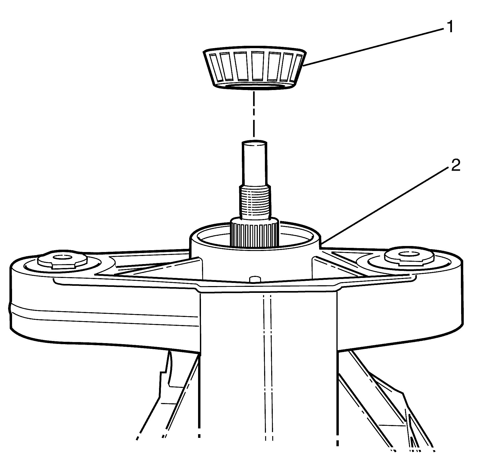
- Position the NEW pinion head bearing (2) onto the pinion gear (1).
- Press the NEW pinion head bearing (2) onto the pinion gear using DT-48807 (3).
- Clean the ring gear and the contact area of the differential.
- Position the NEW head bearing cup (1) into the differential housing (2).
- Press the NEW head bearing cup in with DT-48723 (1) and rotate until it fits tightly in the front differential housing (2).
- Use a feeler gauge to make sure the NEW head bearing cup is seated correctly.
- Position the NEW tail bearing cup (2) to the differential housing (3).
- Press the NEW tail bearing cup in with DT-48725 (1) and rotate until it fits tightly in the front differential housing (2).
- Use a feeler gauge to make sure the NEW tail bearing cup is seated correctly.
- Position the ring gear (1) to the differential (2).
- Install two NEW ring gear to differential retaining bolts.
- Install the remaining NEW ring gear to differential retaining bolts (1).
- Press the right differential bearing (1) to the differential (3) with DT-48728 (2).
- Rotate and press the left bearing to the differential with DT-48728 (2).
- Position the differential (1) to the differential housing (2).
- Position the left shim (3) and right shim (1) to the original position in the differential housing (2).
- Position the differential housing cover to the differential housing and retain with the 4 bearing bolts (1).
- Turn the differential assembly left through 90° for the differential to slide down in the housing.
- Install the circlip (1) to the differential (3) with circlip pliars (2).
- Make sure the circlip (1) is fitted correctly.
- Install the remaining differential housing cover to differential housing retaining bolts (1).
- Position the backlash tool (1, 4) to the differential assembly (3).
- Secure the backlash tool (1) to the differential assembly (3) by adjusting the spreading nut (4).
- Mount the turning torque gauge (2) to the backlash tool (1).
- Rotate the turning torque gauge (2) clockwise and record reading.
- Turning torque should be between 2.0 to 3.3 Nm (27 lb in).
- If the measured turning torque is outside the tolerance:
- Remove differential assembly. Repeat steps 5 through 11 from the disassembly procedure.
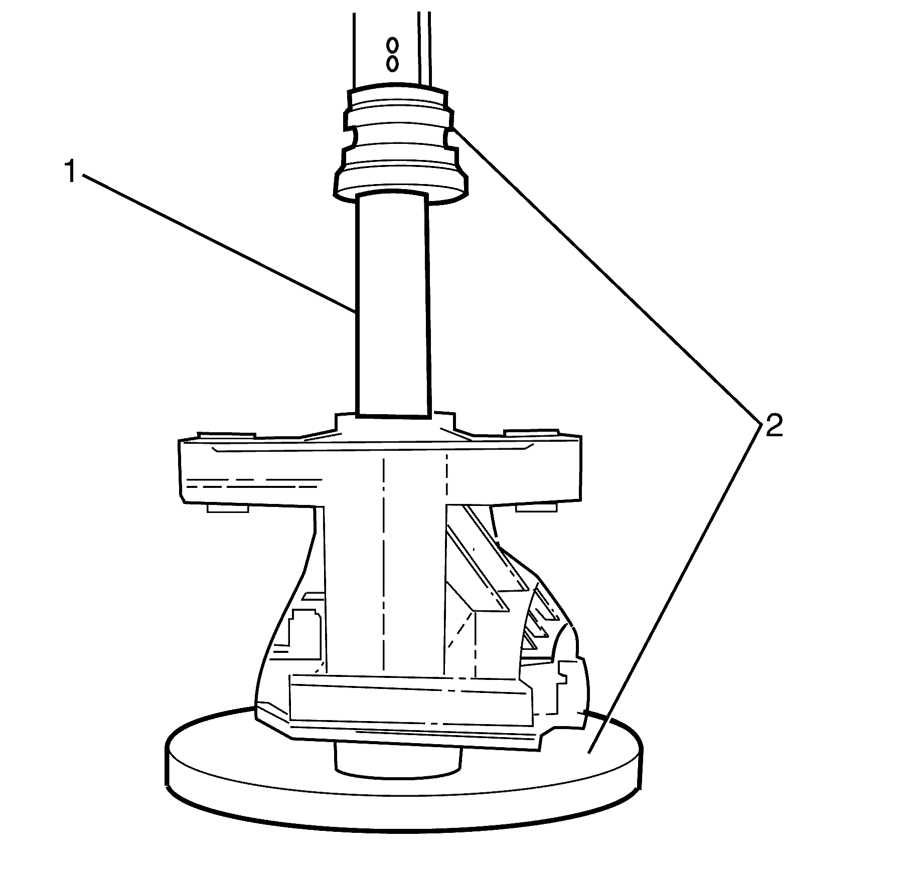
- Position the pinion (4) on DT-48728 (3) in a suitable press (2).
- Position the differential housing (1) over the pinion gear (4).
- Position a NEW collapsible spacer (1) to the differential (2).
- Position the pinion tail bearing (1) to the differential housing (2).
- Use a suitable press (2) and DT-48723 (1) to press the tail bearing until it rests against the collapsible spacer.
- Remove the supporting tool so that the differential housing rests on the table.
- Lubricate the NEW pinion flange seal (1) with correct grease. Refer to Adhesives, Fluids, Lubricants, and Sealers .
- Install the pinion flange seal (1) to the differential housing (4) with DT-48727 (2) in a suitable press (3).
- Mount the differential housing (4) on a suitable holding device.
- Position the pinion flange (2) to the differential (3).
- Lubricate the contact surface of the prevailing torque pinion flange retaining nut (1) with correct grease. Refer to Adhesives, Fluids, Lubricants, and Sealers .
- Apply correct loctite to the thread of the NEW prevailing torque pinion flange retaining nut (1).
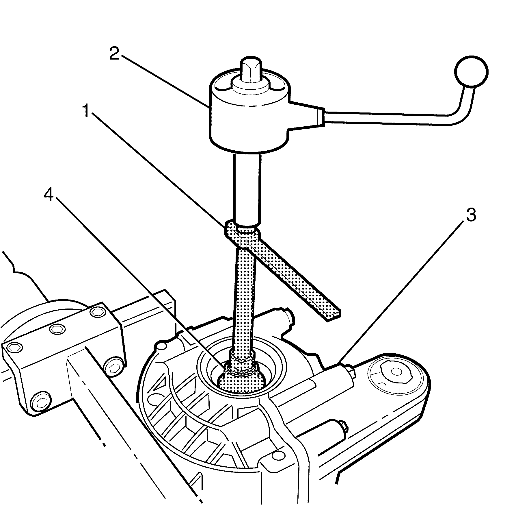
- Install the NEW prevailing torque pinion flange retaining nut (1) to the differential (3).
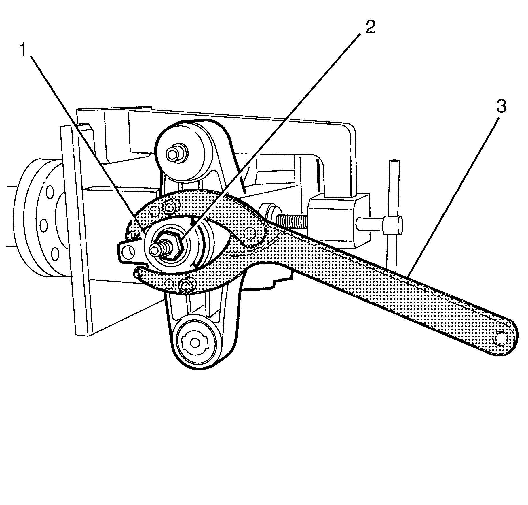
- Install the universal pulley holder (3) to the pinion flange (1).
- Tighten the prevailing torque pinion flange retaining nut (2) carefully until it has no play.
- Remove the universal pulley holder from the pinion flange (1).
- Turn the differential assembly through 90°.
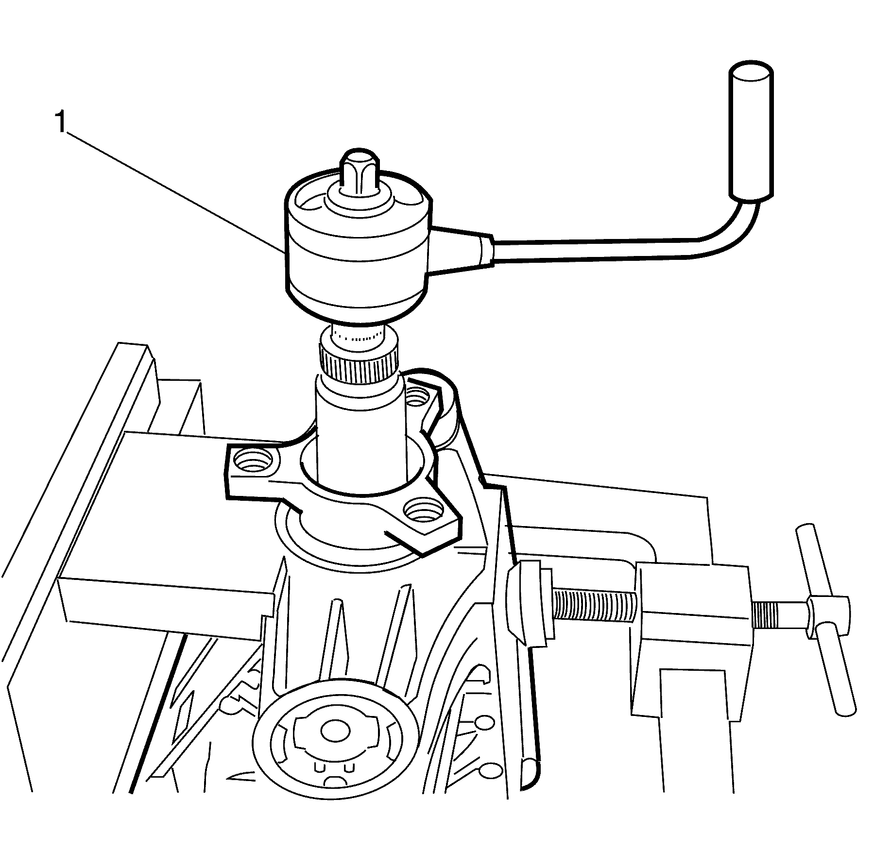
- Position the turning torque gauge (1) to the prevailing torque pinion flange nut.
- Turn the turning torque gauge (1) in a clockwise direction and record reading.
- Turning torque should be between 2.2 and 2.7 Nm (20-25 lb in).
- If the turning torque is below specified tolerance, tighten the prevailing torque pinion flange retaining nut in small steps and check turning torque until specified turning torque is reached.
- If the turning torque is above specified tolerance disassemble, fit new collapsible spacer and repeat until correct specification is achieved.
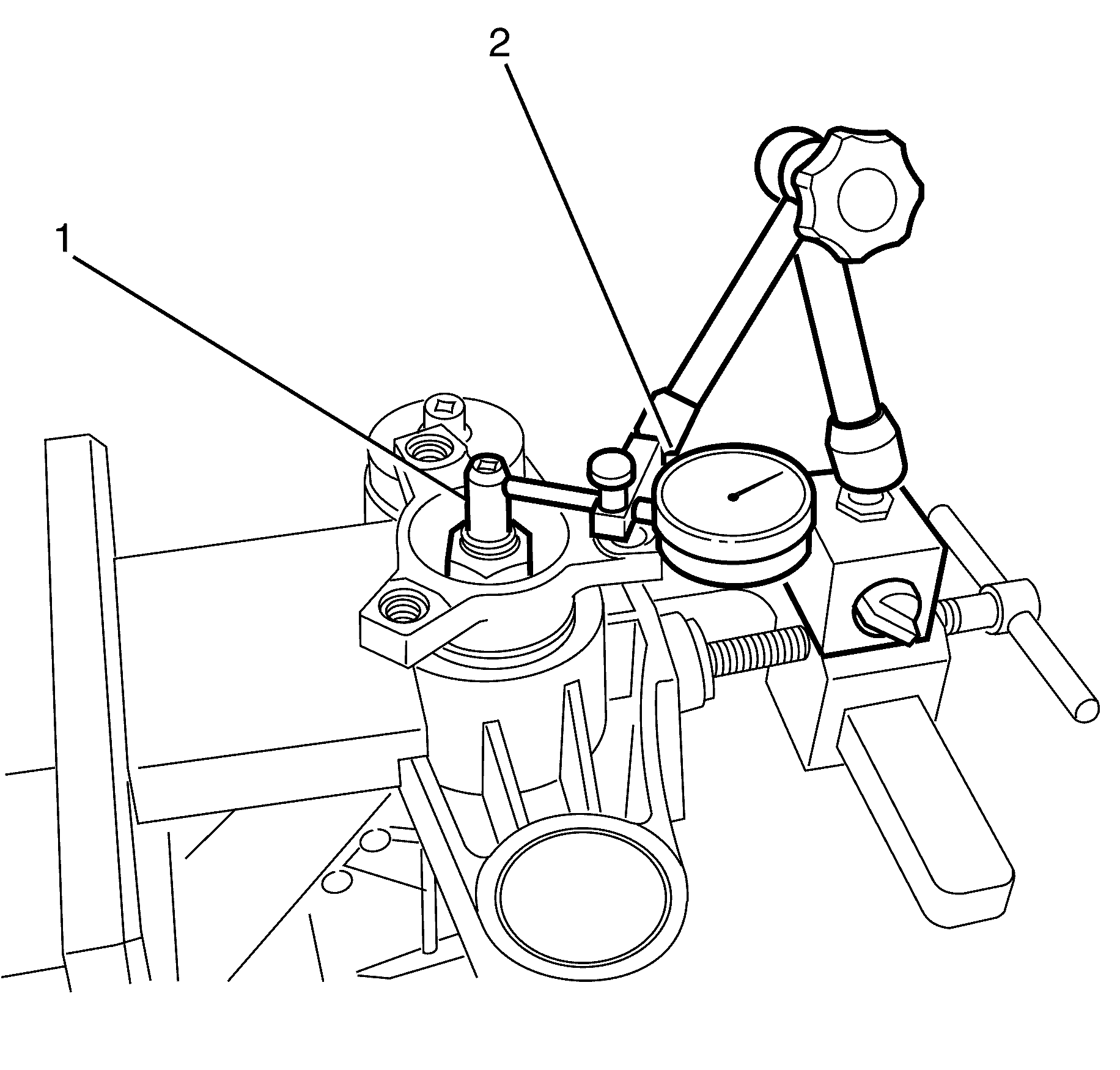
- Position a dial gauge (2) to measure the concentric running on centering while turning the pinion (1).
- If the measured value is above .1mm remove the pinion flange and re-install at a different angle. Repeat steps 52-66 in the assembly procedure. Make sure the turning torque is .1-.2 N-m higher than recorded in step 63 but not higher than 2.7 N-m.
- Position the backlash tool (2) to the differential assembly.
- Position the dial gauge (1) to the backlash tool (2).
- Use a suitable tool to move the backlash tool (2) within the backlash and record the reading.
- Backlash must be between .07 and .18 mm.
- If the backlash is not between the specified tolerance, it must be adjusted with differential shims otherwise turning torque set during steps 38-43 will be changed.
- If a .05 mm thinner shim is used on the right a .05 mm thicker shim has to be added to the left.
- Remove the rear differential housing. Refer to steps 5 and 6 in the disassembly procedure.
- Clean the mating faces of the differential housings (2).
- Apply a 1mm liquid seal bead (loctite 5910).(1) to the mating face of the differential housing. Refer to Adhesives, Fluids, Lubricants, and Sealers .
- Install the differential housing cover to the differential housing. Refer to steps 26 through 33.
- Install the left and right rear axle shaft seals (1) using DT-48722 and DT-48721 (2).
- Install two rear axle flanges or two sealing plugs (1) to seal the differential (3).
- Remove the oil drain plug and install the air pressure regulator (2).
- Connect the air supply to the regulator (2) and pressurise the differential (3) to .4 bar.
- Disconnect the air supply from the regulator (2).
- The pressure should not decrease from .4 bar within 3 minutes. If the pressure decreases, locate and repair leakage.
- Install the differential (3) to the vehicle. Refer to Differential Replacement .
- Fill the differential fluid. Refer to the filling procedure in Differential Oil Replacement .
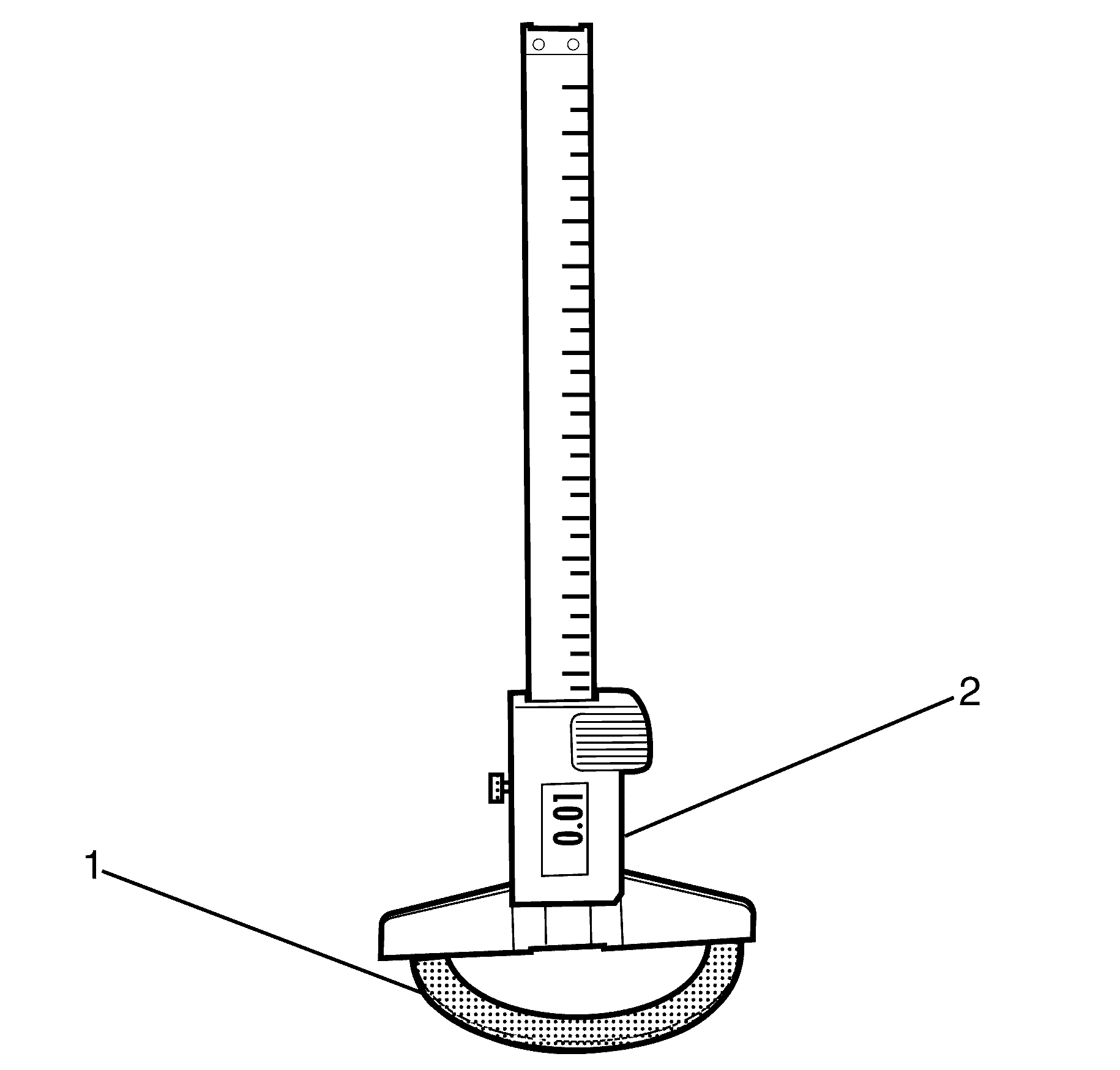
Important: Use DT-48806 otherwise bearing height cannot be measured correctly.
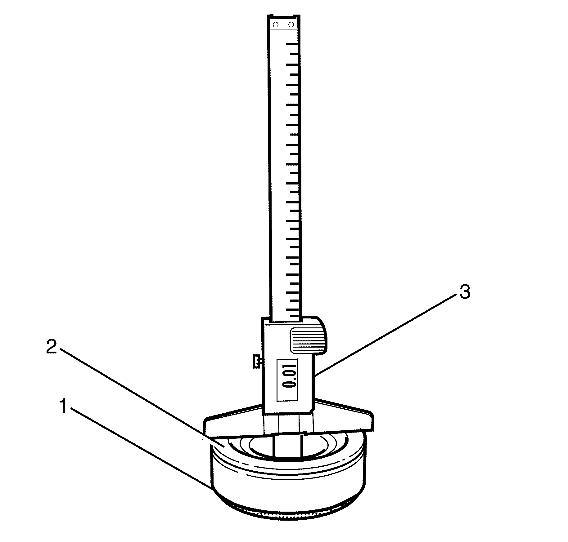
Important: Rotate the pinion head bearing (2) to settle for correct measurement.
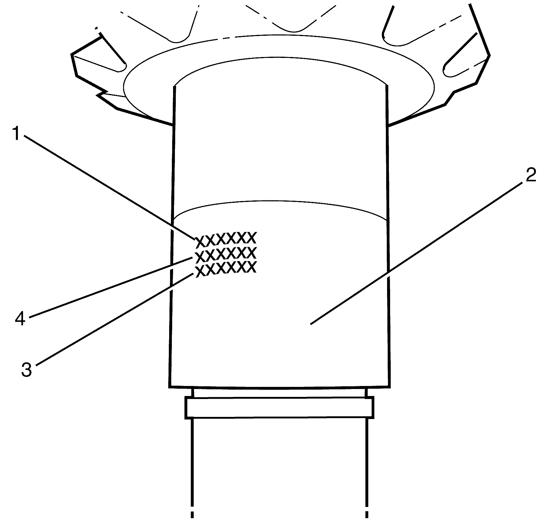
| • | Serial Number A0200008 (1) |
| • | Pinion Size 106.475mm (4) |
| • | Set Number 260125 (3) |
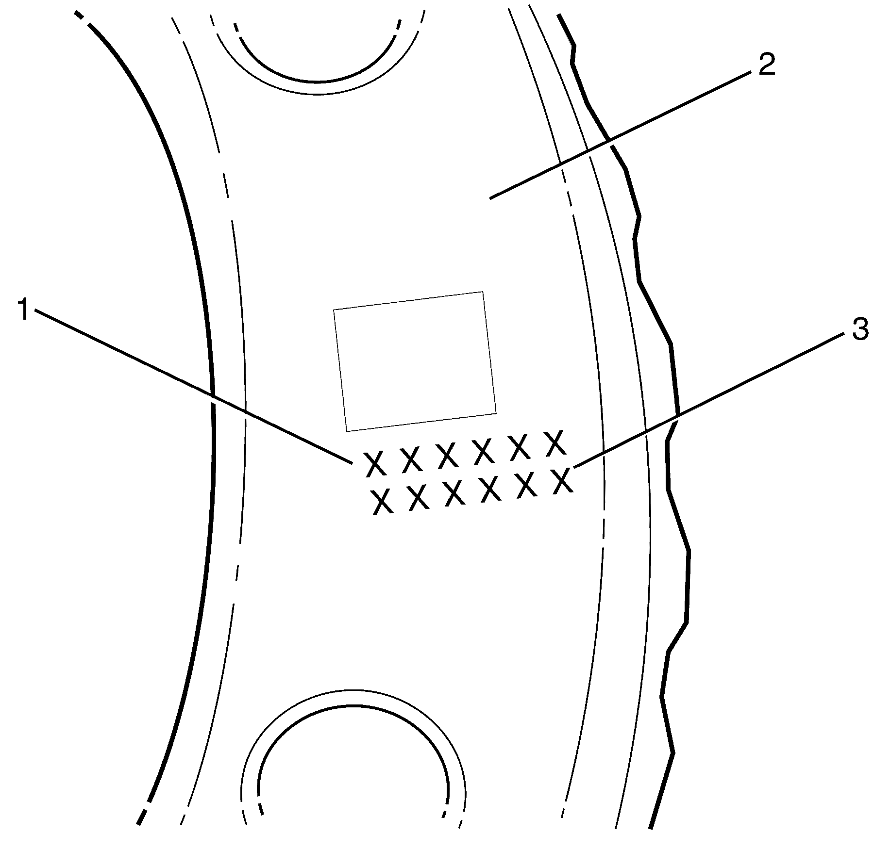
| • | Serial Number A0200008 (1) |
| • | Set Number 260125 (3) |
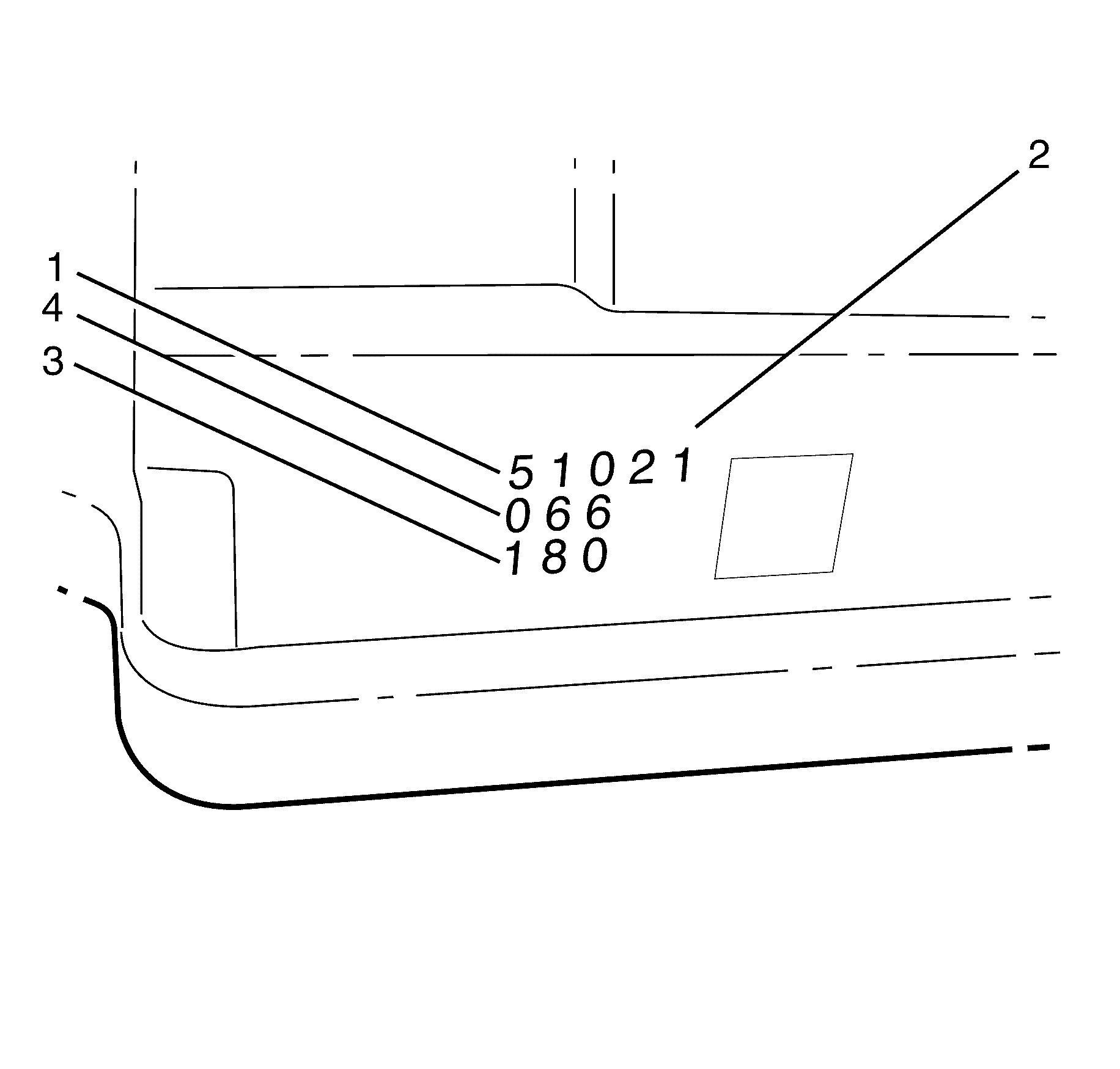
Important: The identification number (1, 3, and 4) is stamped into the differential housing (2).
| • | Manufacturing date (1). |
| • | Item number (4). |
| • | Size equals 138 plus the number on the housing. Example - 138.180mm (3). |
| • | Add the pinion plus the bearing Example - 106.475mm + 30.255mm = 136.730mm. |
| • | Subtract the pinion plus the head bearing from the housing size, also subtract the correction factor. The correction factor is .05mm. Example 138.180 - 136.730 - 0.05 = 1.40mm thickness shim required. |
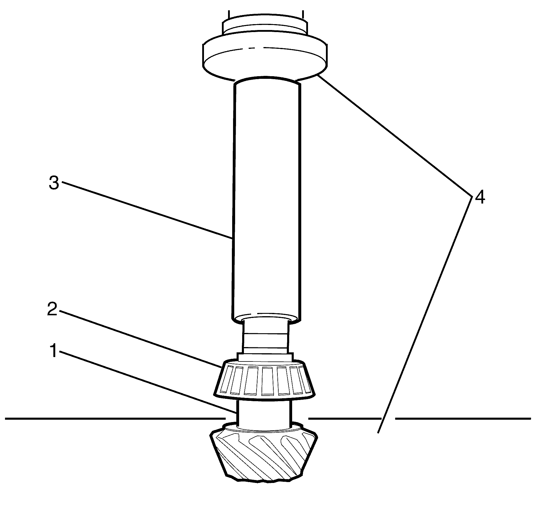
Important: Use DT-48807 (3) to aid in pinion bearing (2) installation.
Important: Position the pinion gear (1) onto an aluminium plate in suitable press (4) before pressing the pinion head bearing (2) to prevent damage to the pinion (1).
Important: Use a suitable press (4) to install the NEW differential pinion head bearing (2).
Caution: Refer to Safety Glasses Caution in the Preface section.
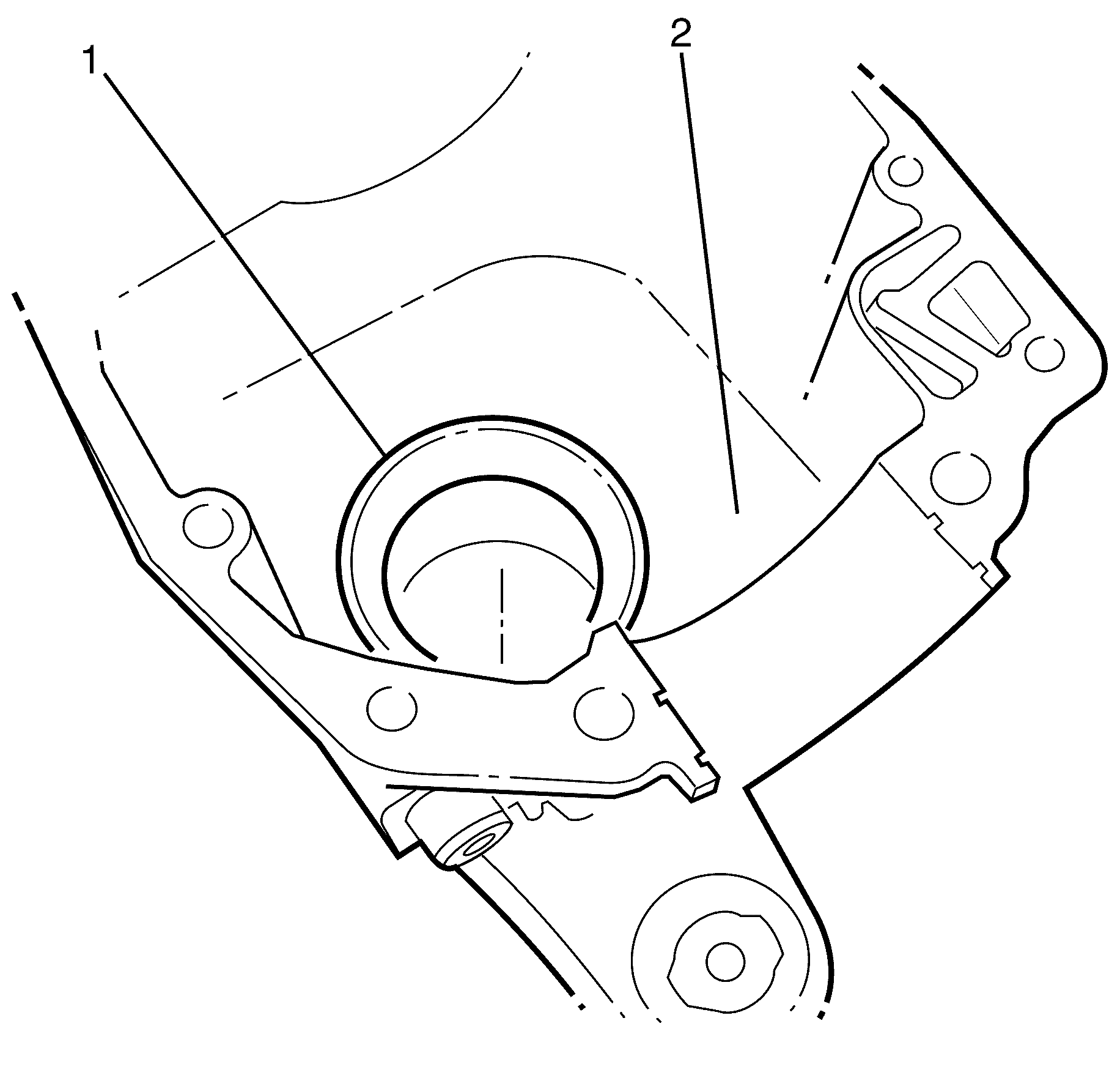
Important: To make fitting easier cool the bearing cups (2).
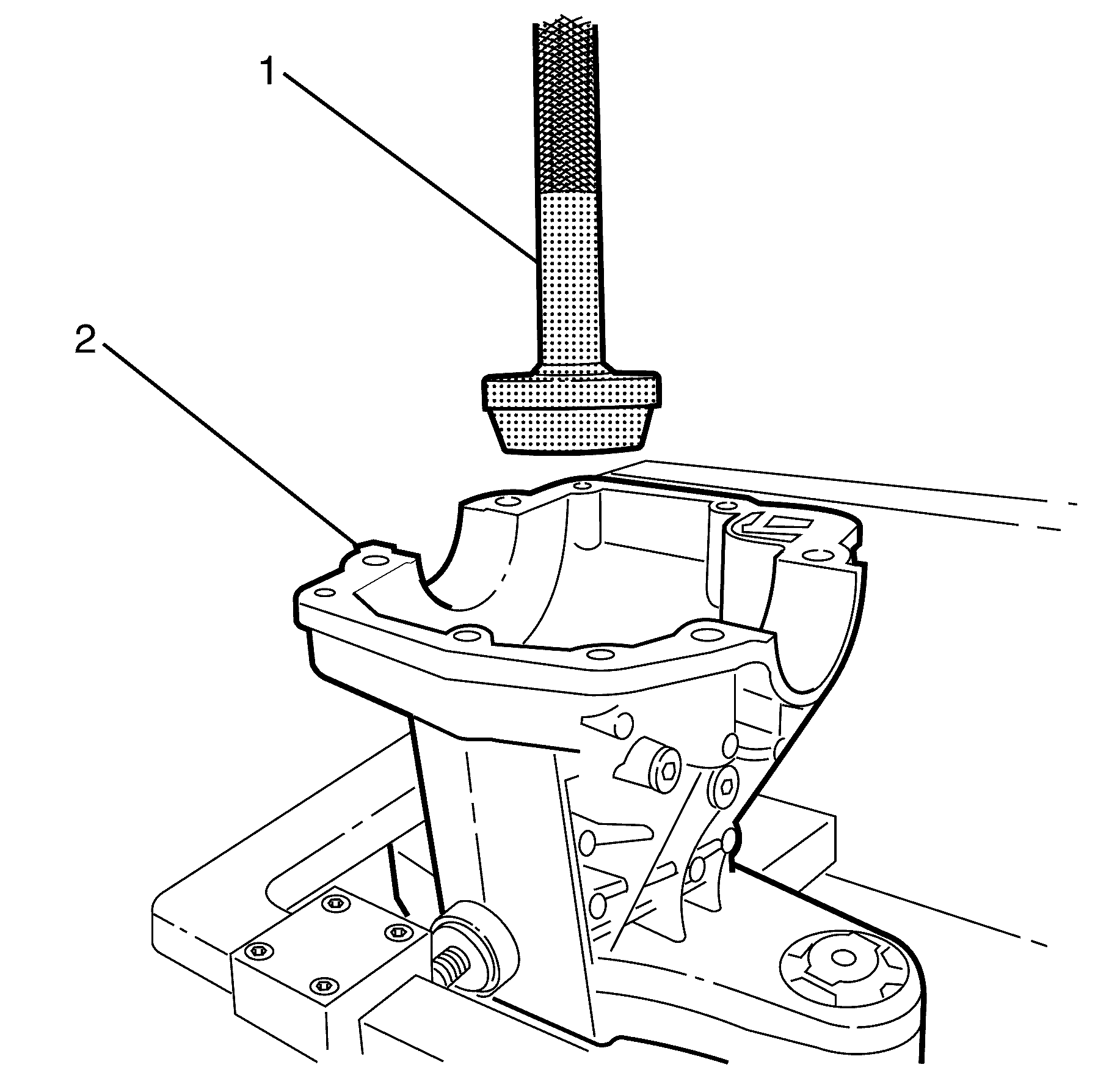
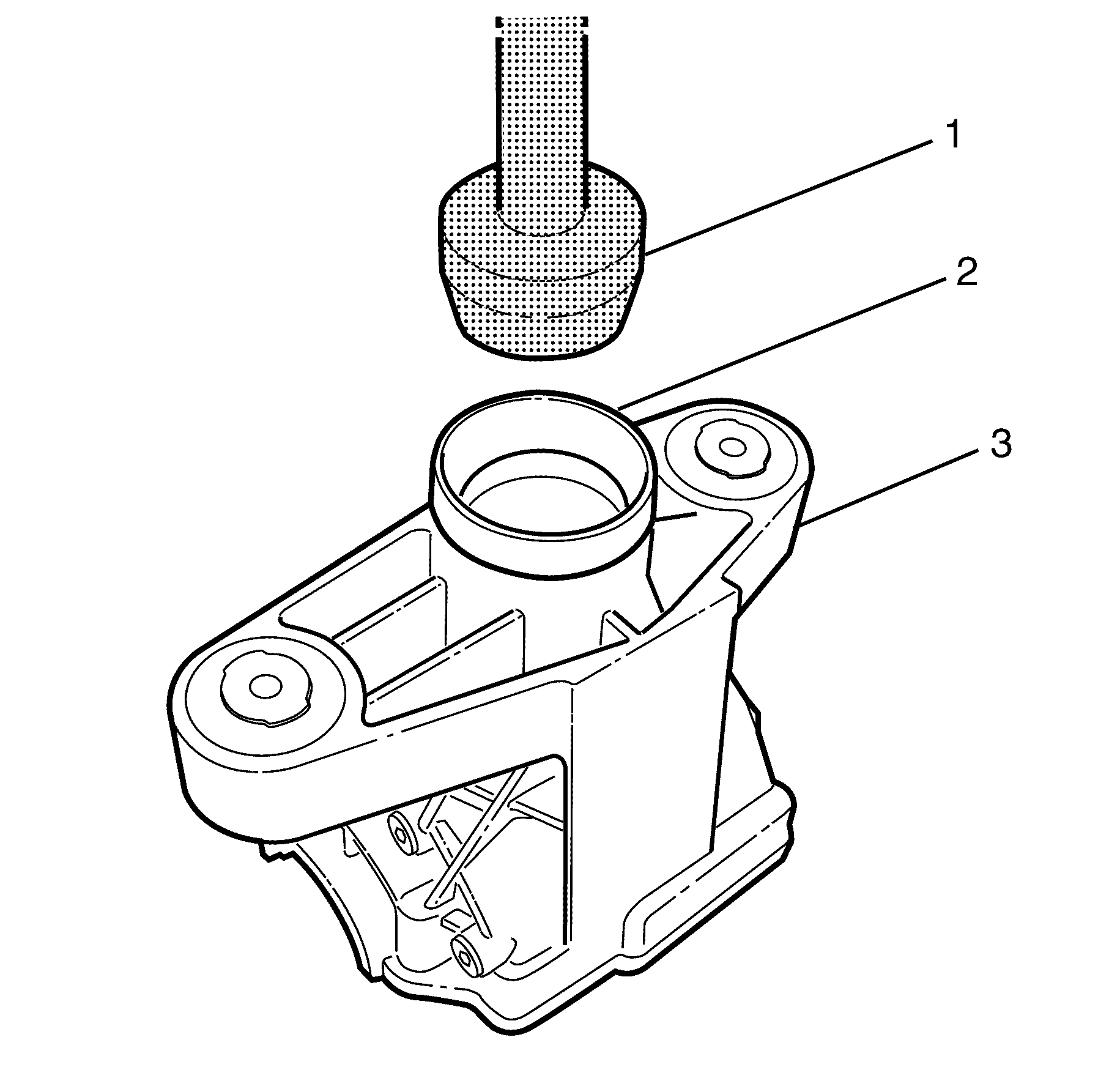
Important: To make fitting easier cool the bearing cup (2).
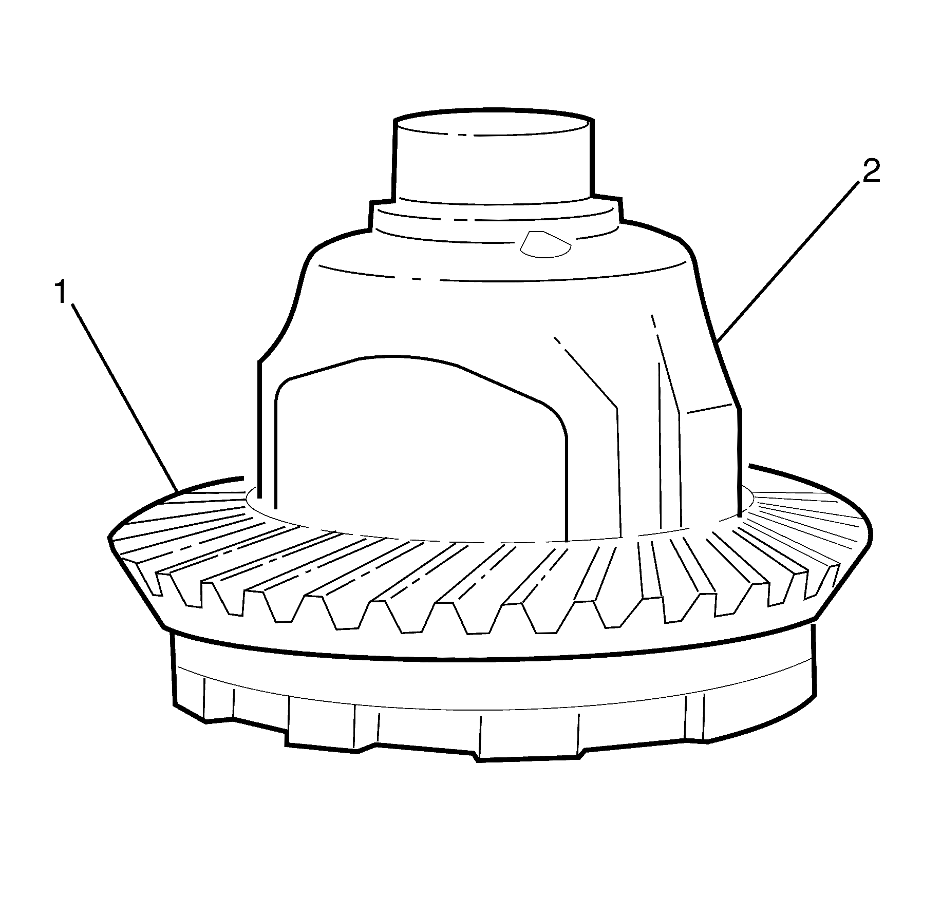
Important: Warm the ring gear (1) evenly using a hotplate until it fits over the differential (2).
Important: Do not fully tighten the NEW ring gear to differential retaining bolts at this stage.
Important: The ring gear has to cool before the ring gear to differential retaining bolts can be tightened.
Notice: Refer to Fastener Notice in the Preface section.
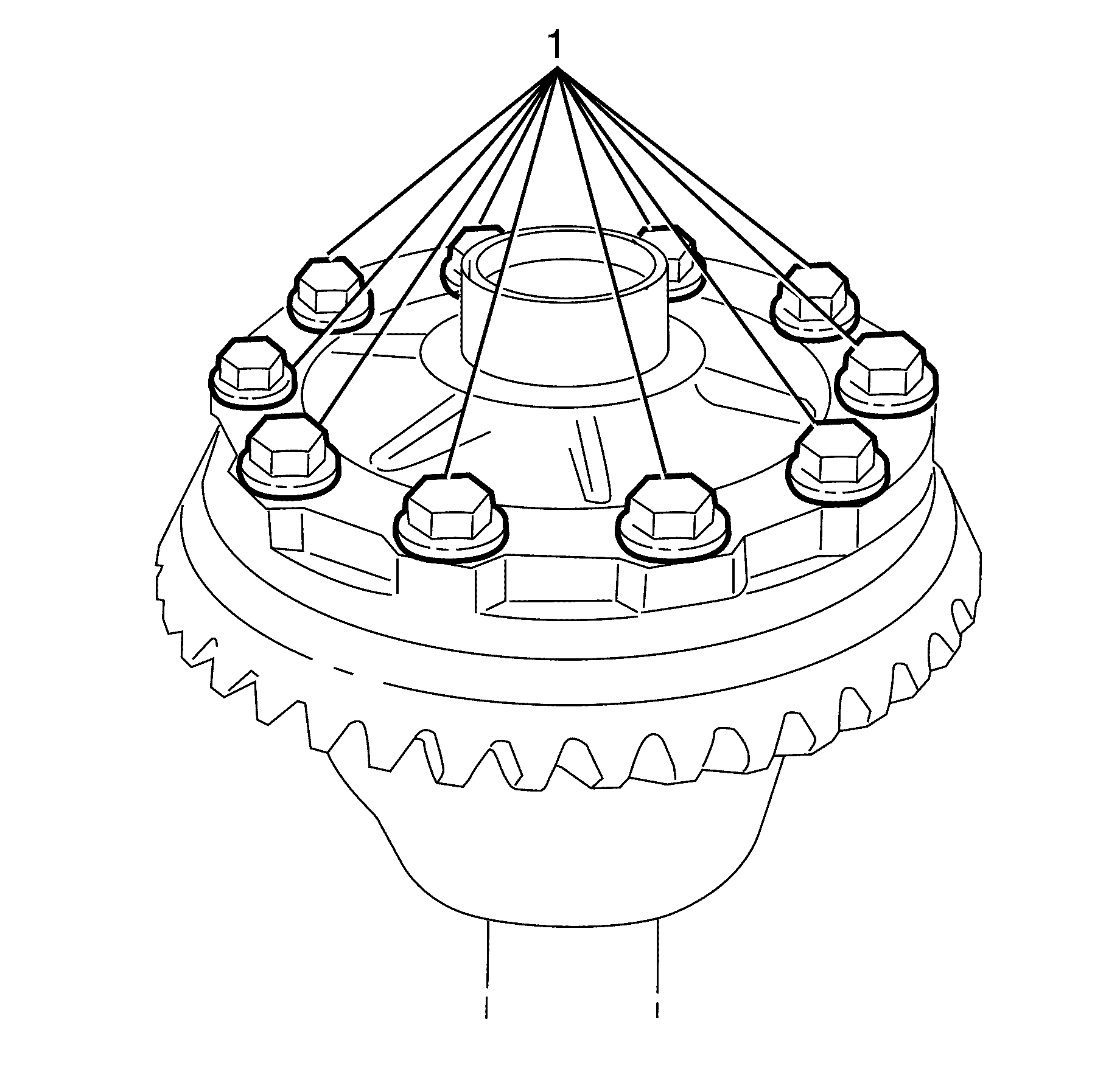
Important: The ring gear has to cool before the ring gear to differential retaining bolts (1) can be tightened.
Important: Tighten the ring gear to differential retaining bolts (1) working diagonally.
Tighten
Tighten the bolts to 125 N-m (96 lb ft).
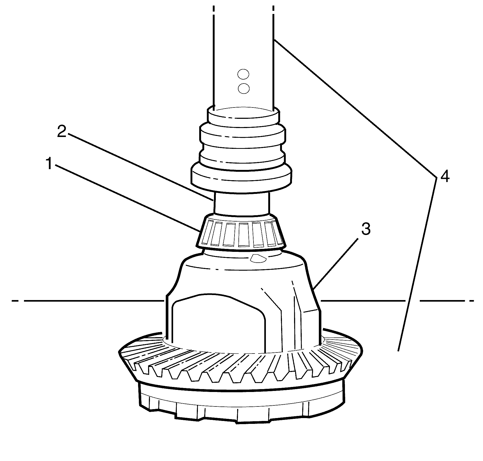
Important: Use a suitable press (4) to install the right differential bearing (1).
Important: Use a suitable press (4) to install the left differential bearing.
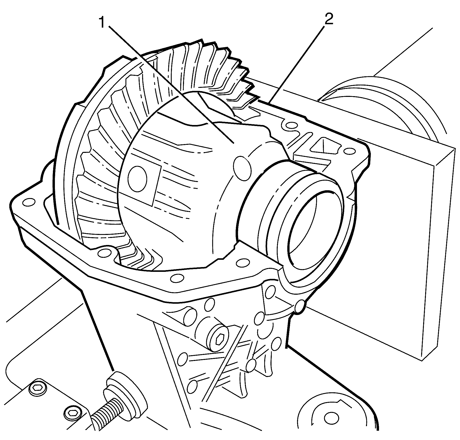
Important: Position the differential (1) to the differential housing (2) using a suitable tool or with the aid of an assistant.
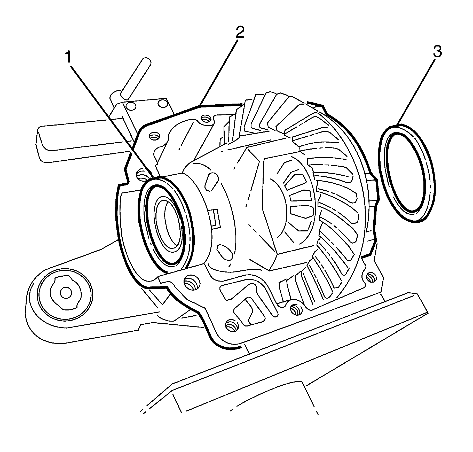
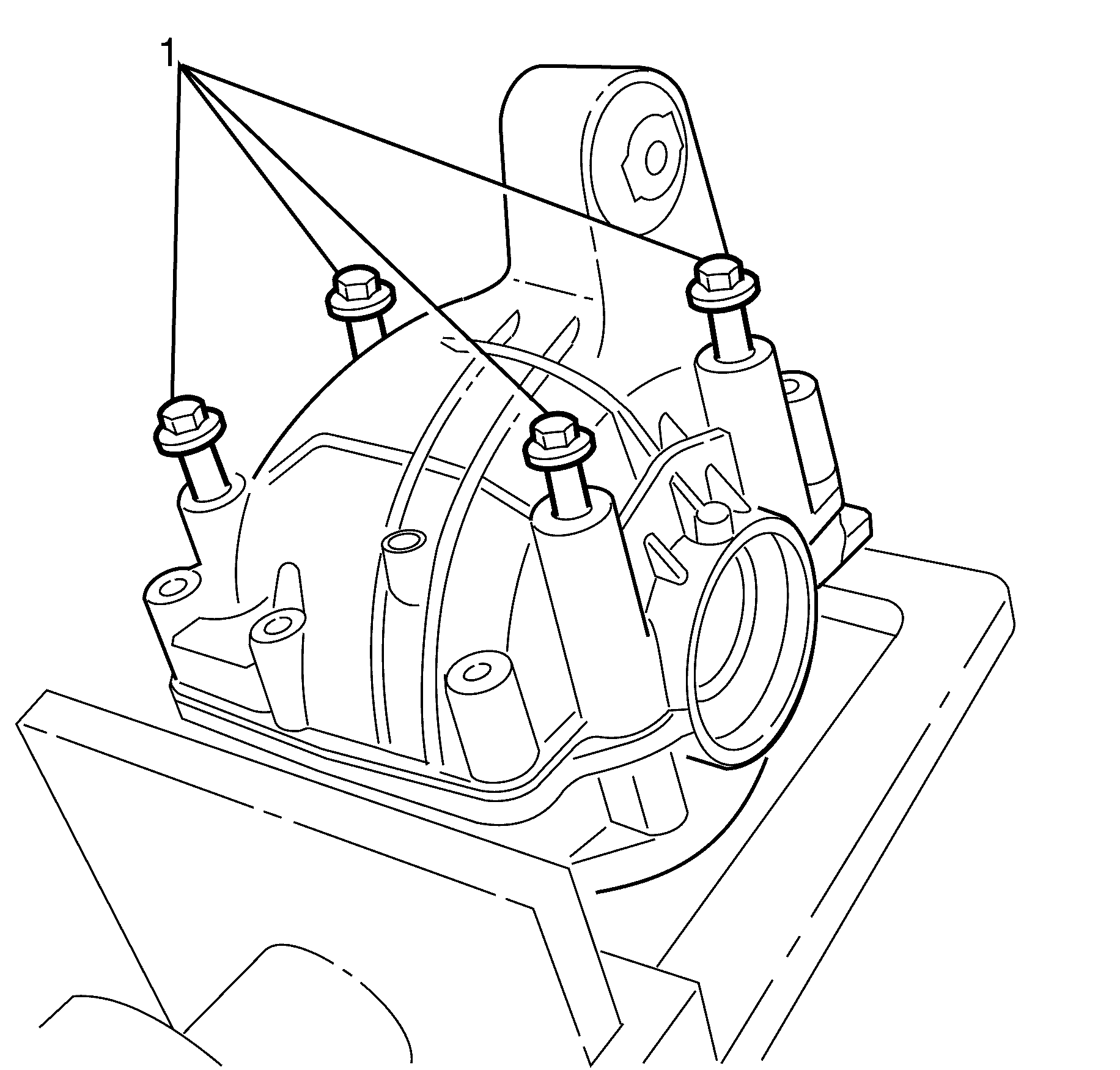
Important: Do not fully tighten the bearing bolts (1) is stage. The differential has to be able to move freely within the differential housing to allow fitment of the circlip.
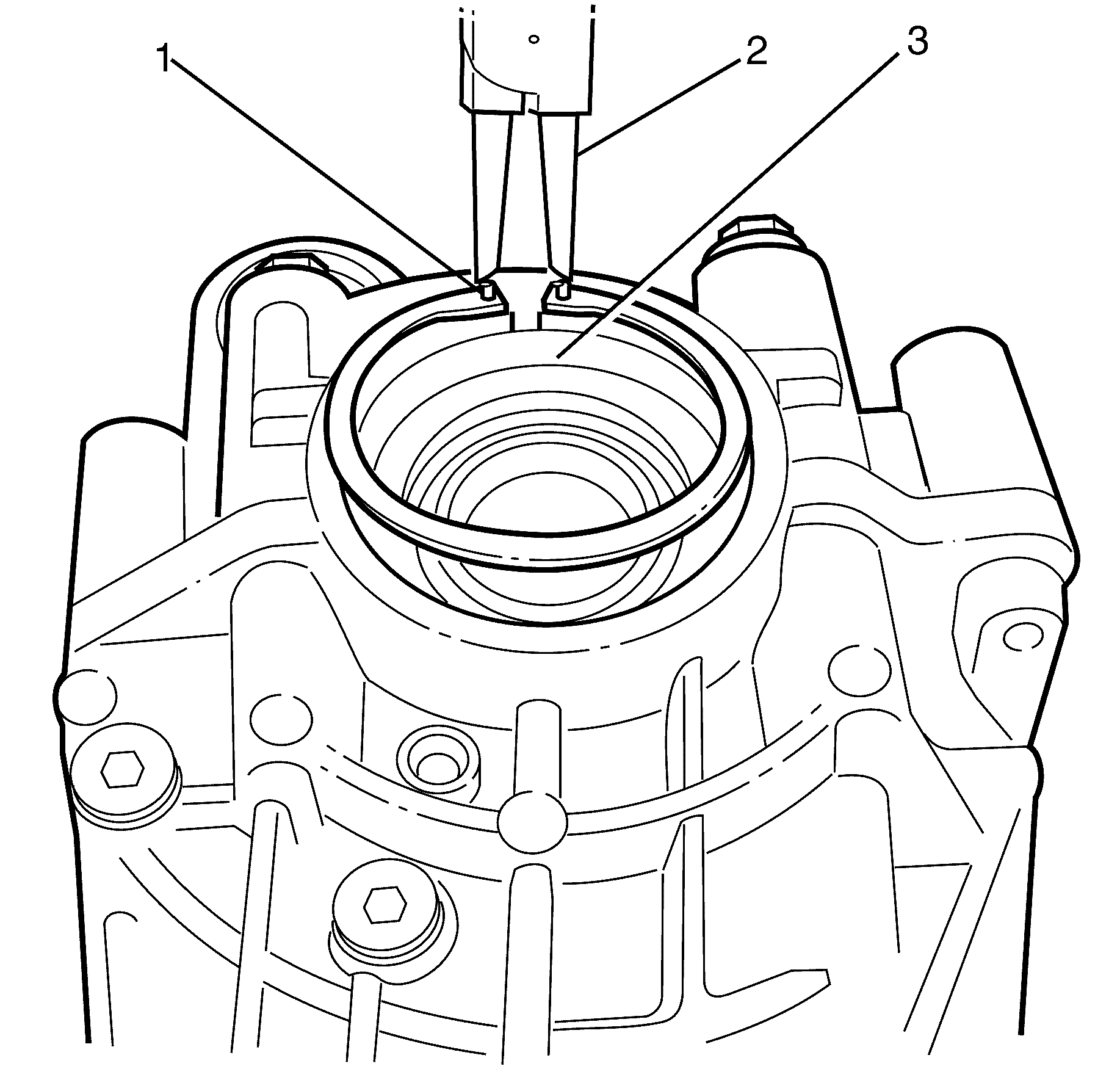
Important: Align the opening of the circlip (1) with the opening on the differential housing.
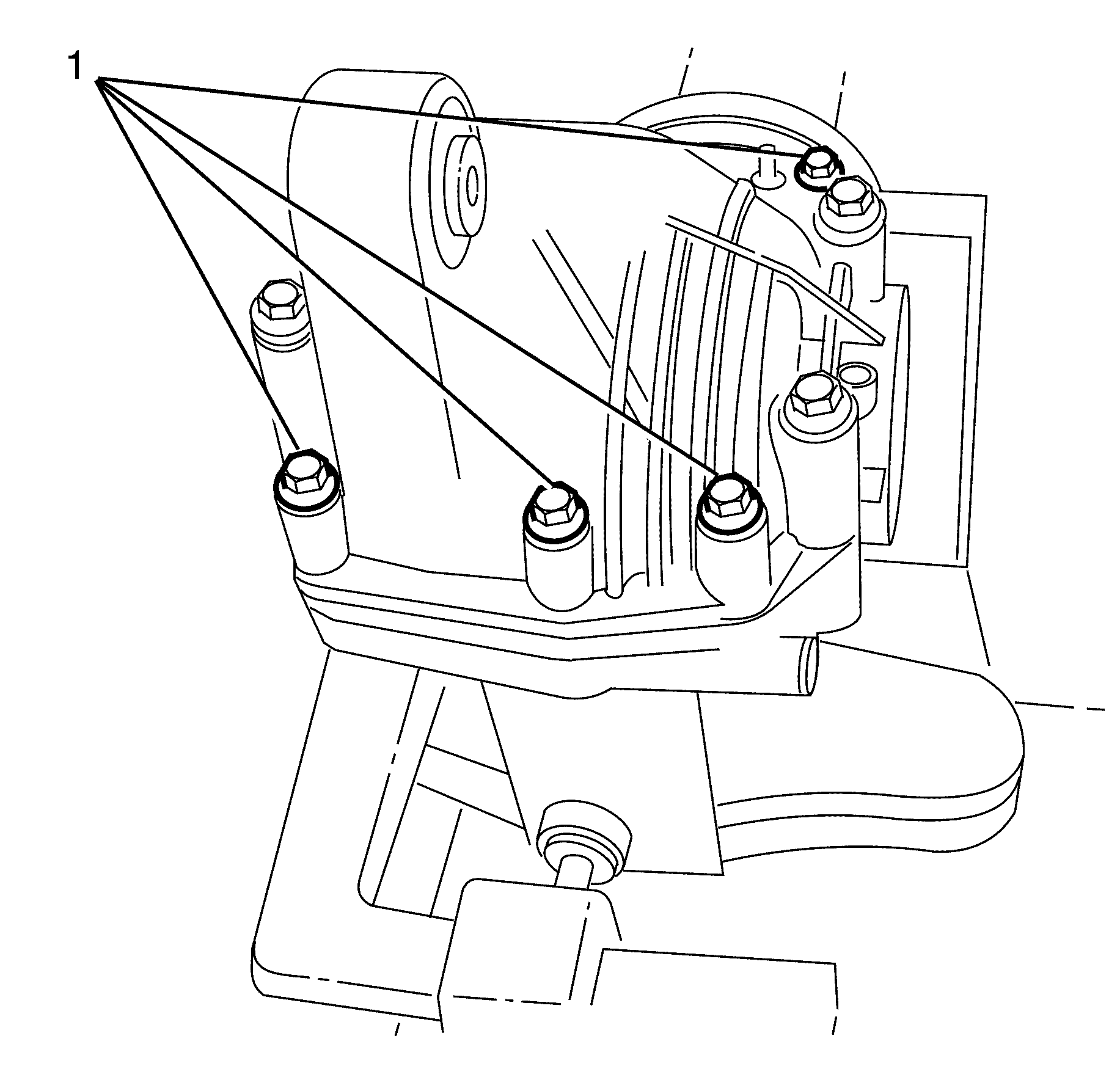
Important: Tighten the differential housing cover to differential housing retaining bolts (1) working diagonally.
Tighten
Tighten the housing bolts to 53 N-m (39 lb ft).
Tighten
Tighten the bearing bolts to 153 N-m (112 lb ft).
Important: This figure is for NEW bearings only.
| • | Remove the rear differential housing. |
| • | If turning torque is too high or too low, fit a thinner or thicker shim respectively. |
| • | Repeat from steps 5-11 from the disassembly procedure then from step 27 onwards in the assembly procedure. |
| • | Check turning torque. Repeat until the turning torque is correct. |
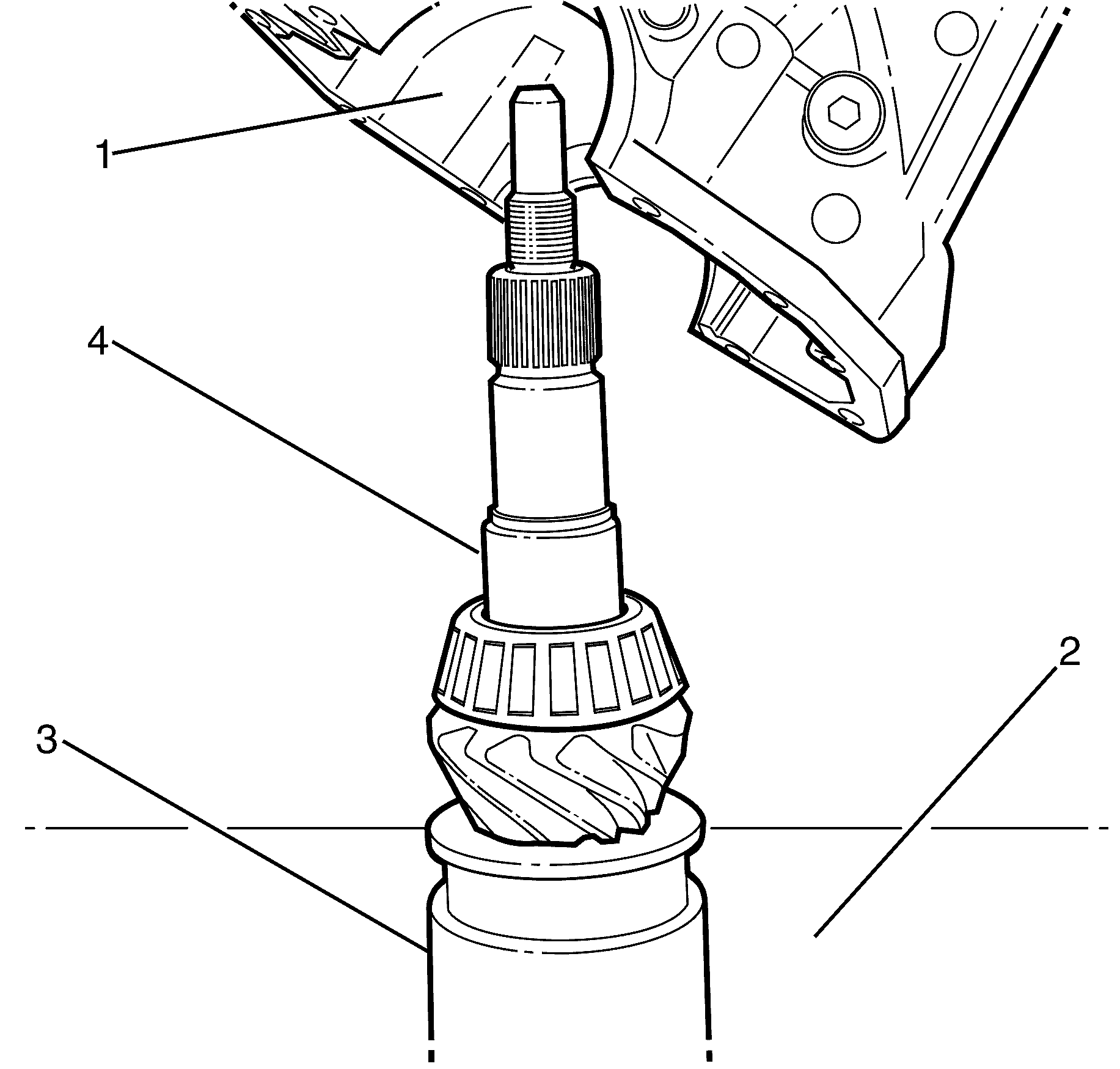
Important: The differential housing (1) must not rest on the press (2). Use a suitable supporting tool (3) to elevate pinion (4).
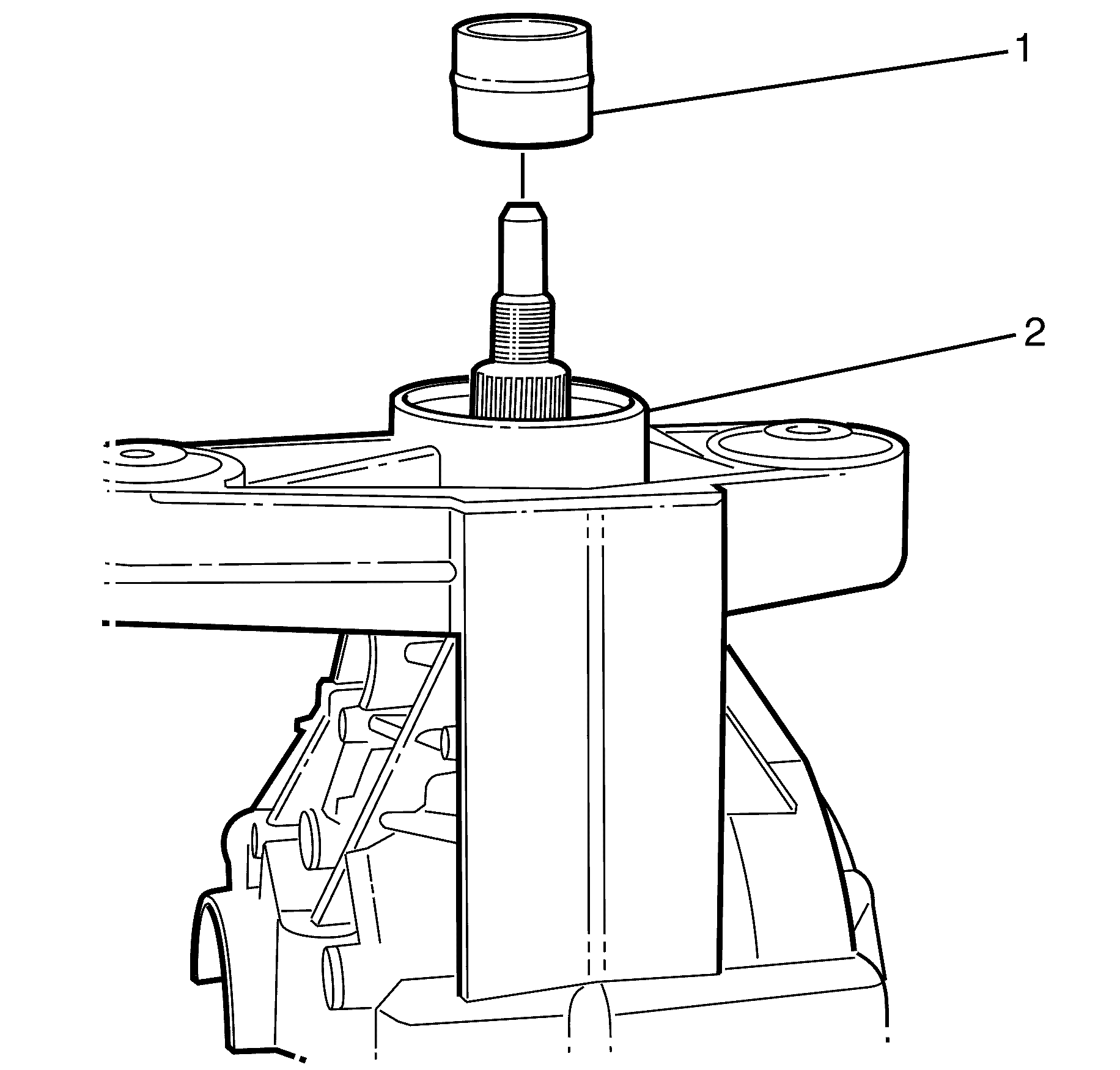
Important: Take care to only press the tail bearing until it rests on the collapsible spacer so that it is not damaged.
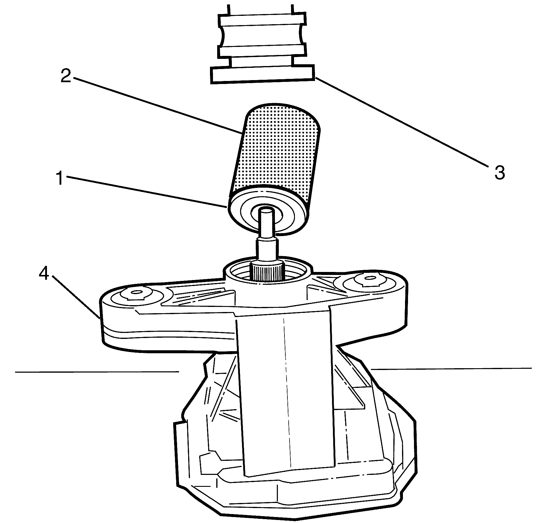
Important: Use DT-48727 to install the seals to correct depth.
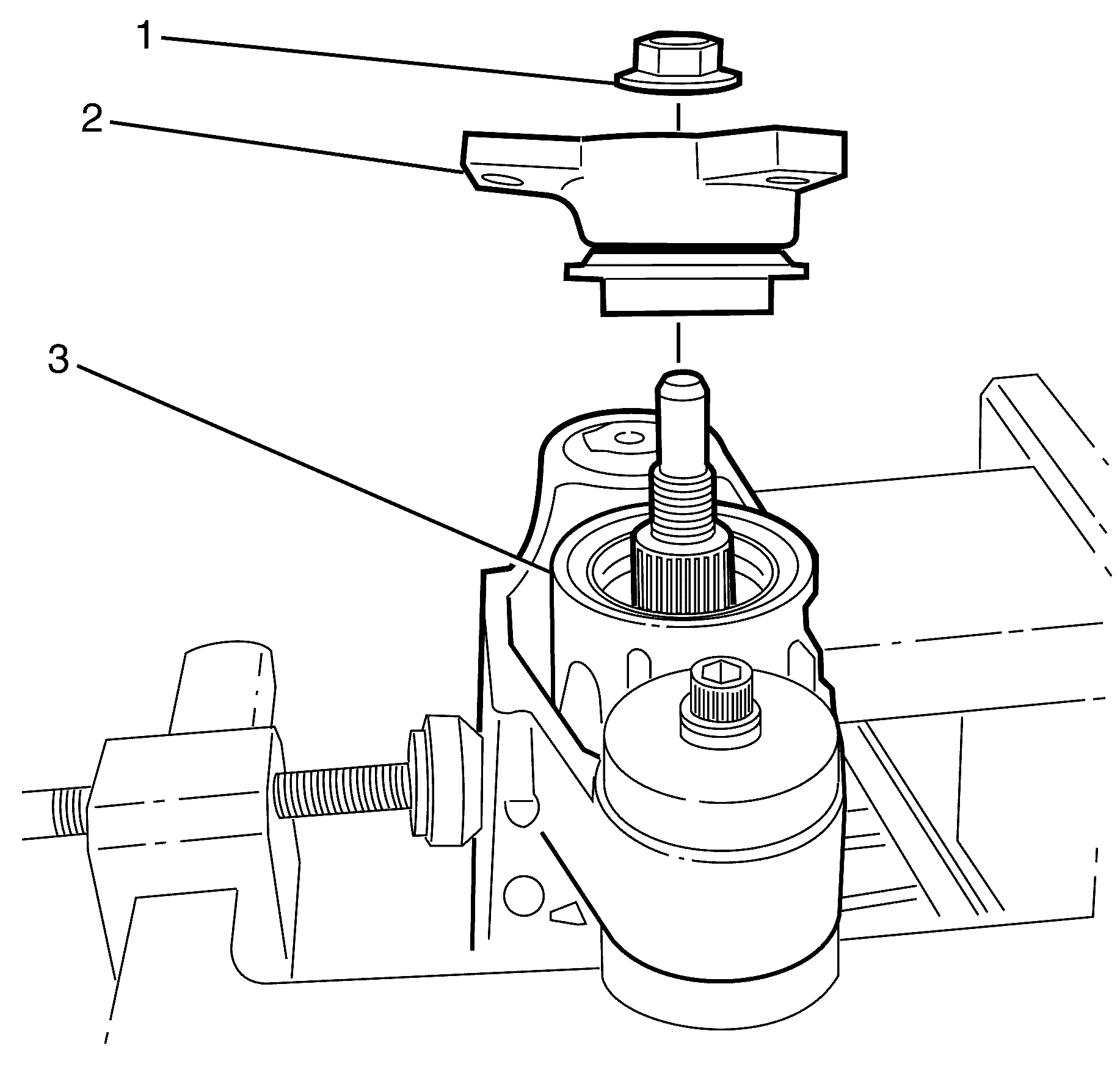
Important: Do not fully tighten the NEW prevailing torque pinion flange retaining nut at this stage. Overtightening will require disassembly and fitment of a new collapsible spacer and possibly bearings.
Important: This torque figure is for NEW bearings only.
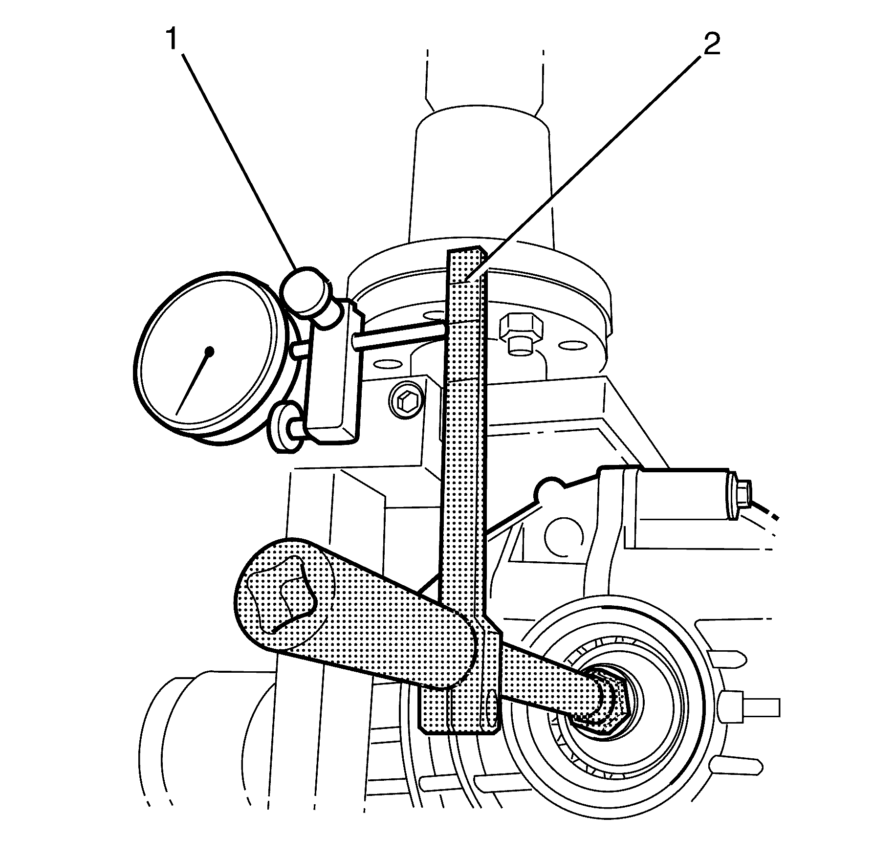
Important: The location of the dial gauge on the backlash tool (2) arm corresponds to the edge of the ring gear (210mm)
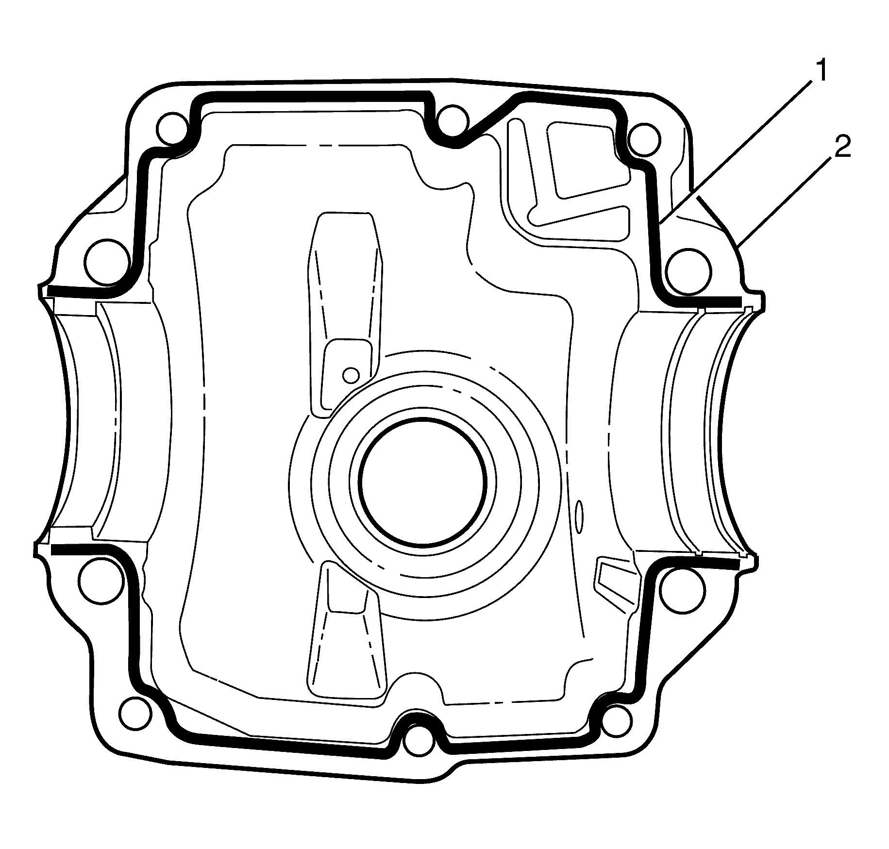
Important: Apply a 1mm liquid seal bead (1) to the differential housing. Use the graphic as a template.
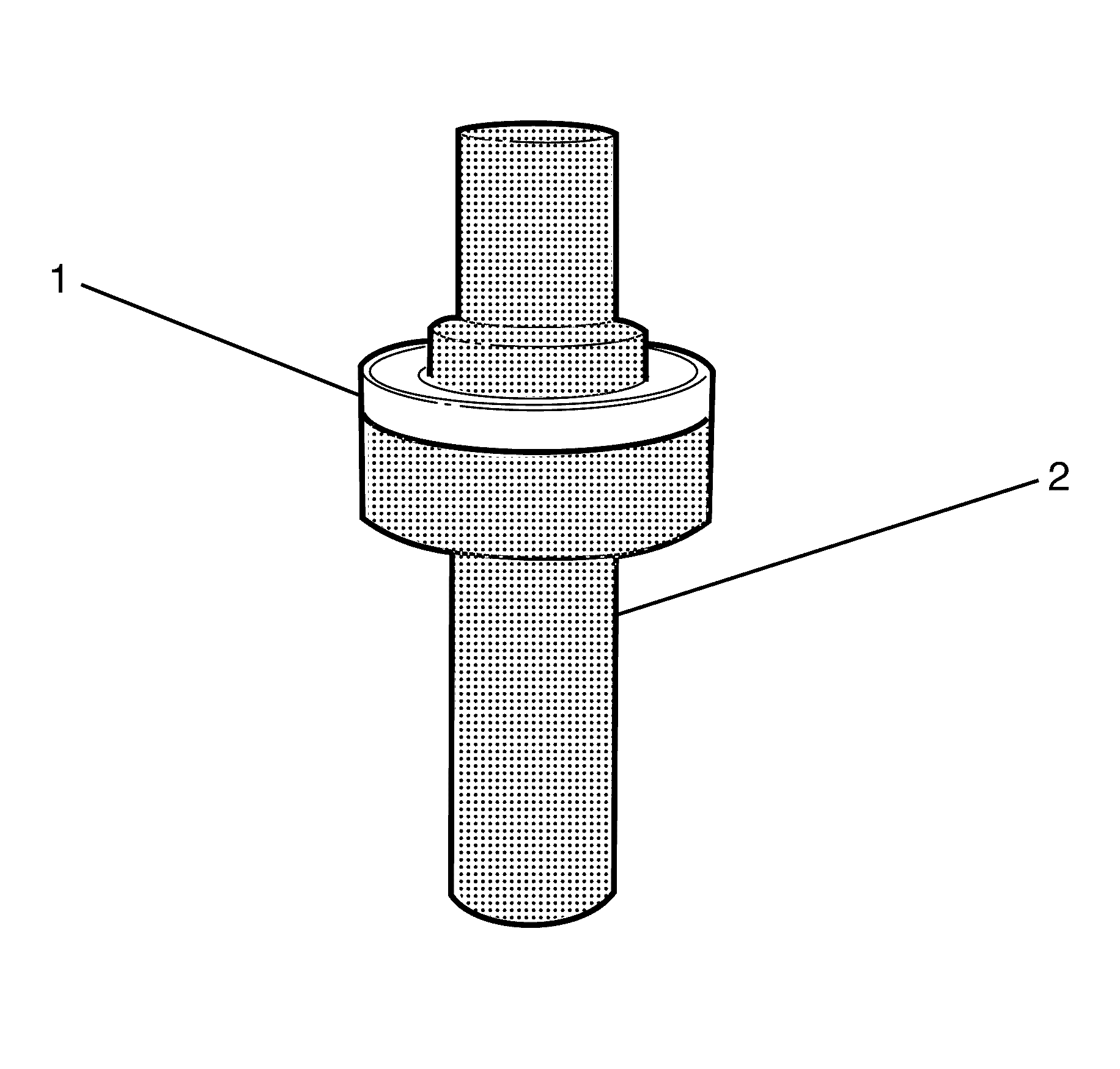
Important: The left and right rear axle shaft seals are different sizes so there are 2 different size installers. Make sure that the correct seal installer is used for the correct seal.
Important: Fill the space between the dust lip and the seal lip with the correct grease.
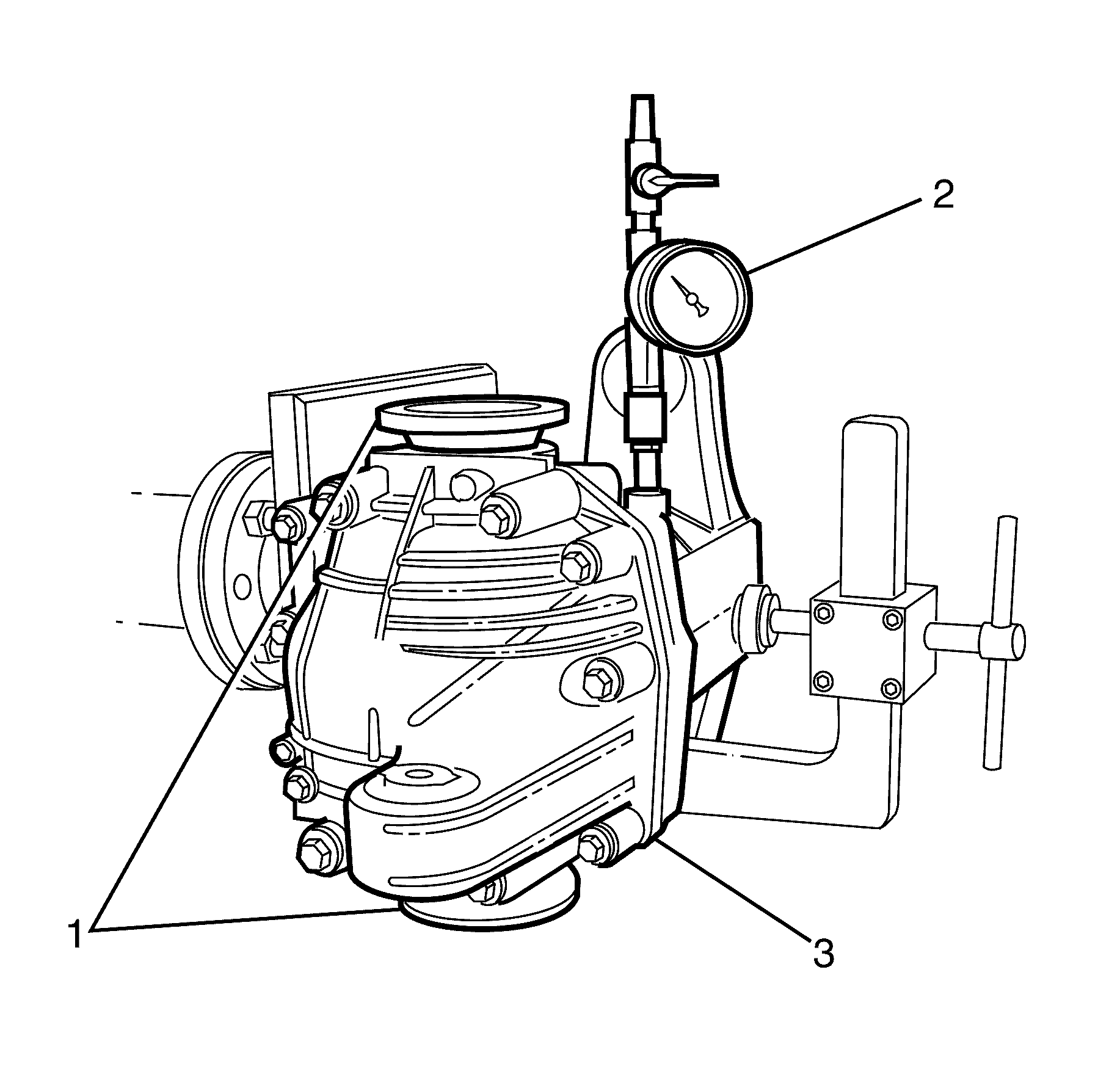
Important: Set the air pressure regulator to .4 bar before connecting.
