Spare Wheel Carrier Replacement Except HSV Maloo
Removal Procedure
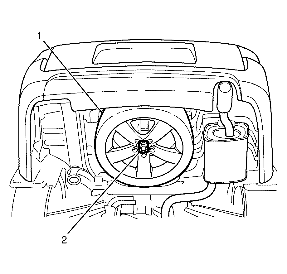
- Remove the spare wheel and tyre (1) from the spare wheel and tyre carrier (2).
- Raise and support the vehicle. Refer to Lifting and Jacking the Vehicle .
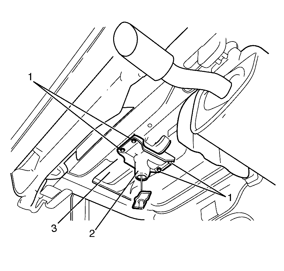
- Remove the spare wheel and tyre carrier to spare wheel and tyre carrier support retaining nuts (1).
- Remove the spare wheel and tyre carrier (2) from the vehicle (3).
Caution: Refer to Safety Glasses Caution in the Preface section.
Caution: Refer to Vehicle Lifting Caution in the Preface section.
Installation Procedure
- Install the spare wheel and tyre carrier (2) to the vehicle (3).
- Install the spare wheel and tyre carrier to spare wheel and tyre carrier support retaining nuts (1).
- Lower the vehicle.
- Install the spare wheel and tyre (1) to the spare wheel and tyre carrier (2).

Notice: Refer to Fastener Notice in the Preface section.
Tighten
Tighten the nuts to 22 N·m (16 lb ft).

Spare Wheel Carrier Replacement HSV Maloo
Removal Procedure
- Raise and support the vehicle. Refer to Lifting and Jacking the Vehicle.
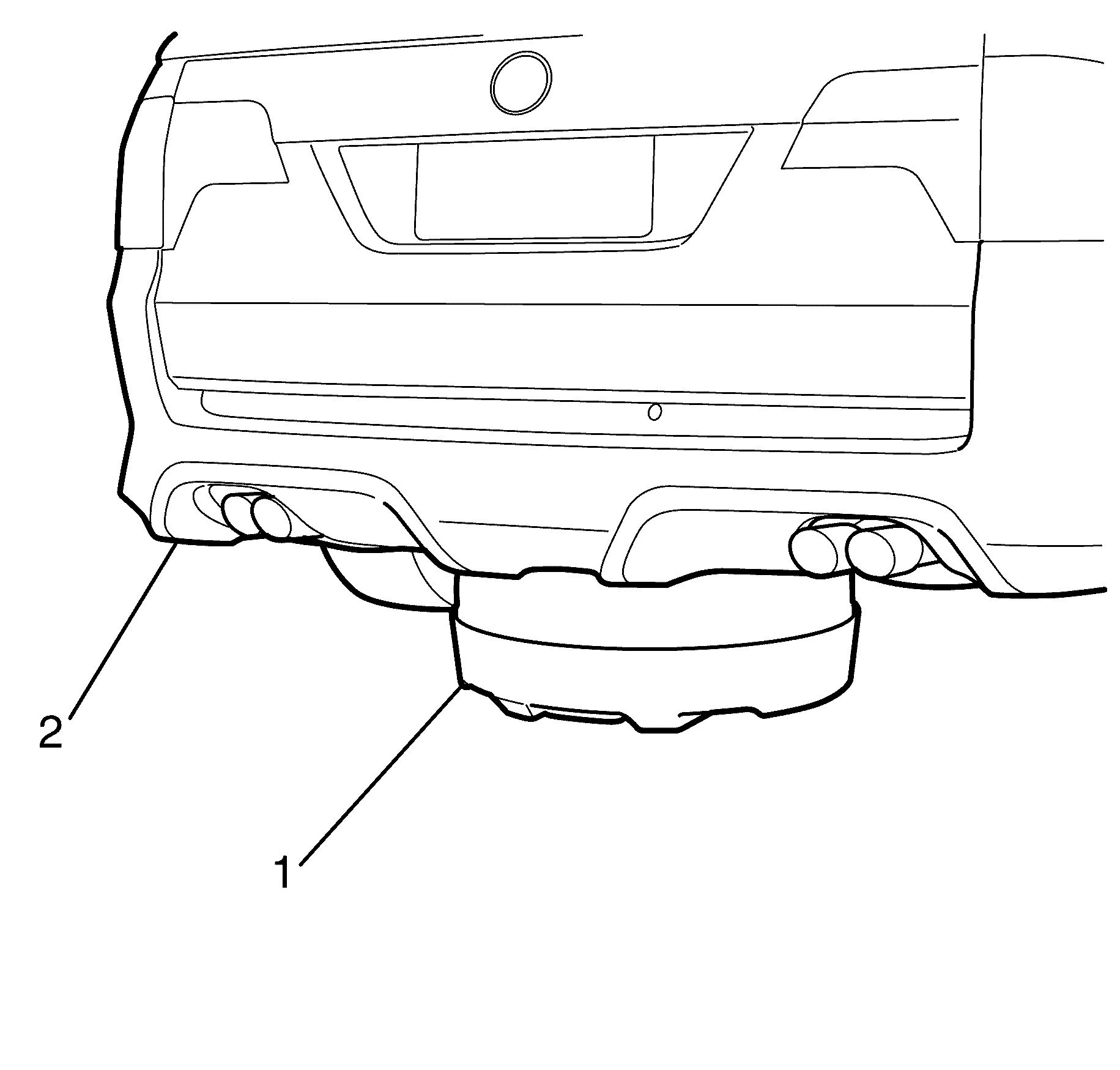
- Use suitable vehicle specific tools to lower the spare wheel carrier (1) downward and away from the vehicle body (2).
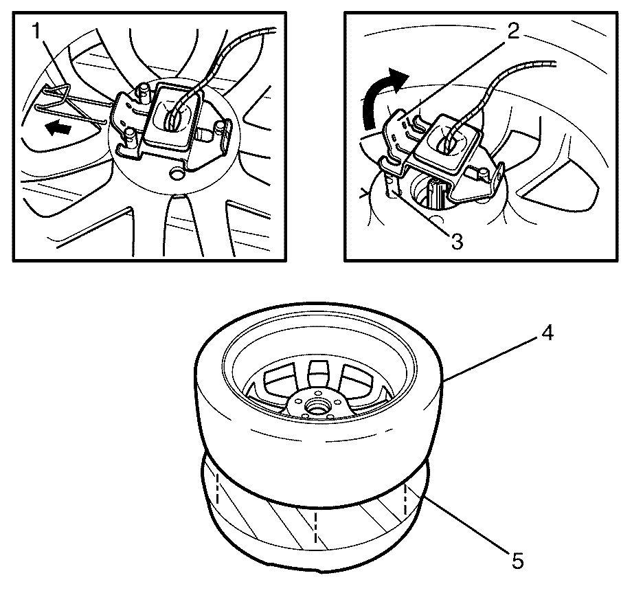
- Disengage the circlip (1), and release the retainer plate (2) from the locating studs (3) inside the spare wheel carrier (5).
- Remove the spare wheel (4) from the spare wheel carrier (5).
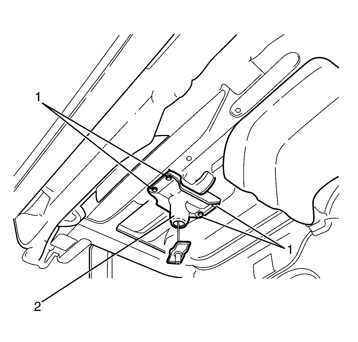
- Remove the tire carrier to spare tire carrier support retaining bolts (1).
- Remove the tire carrier (2) from the vehicle.
Caution: Refer to Safety Glasses Caution in the Preface section.
Caution: Refer to Vehicle Lifting Caution in the Preface section.
Secondary Latch Emergency Release
- Using suitable vehicle specific tools, attempt to lower the spare wheel carrier (1) by inserting the jack handle (2) and extension bar (3) into the spare wheel winch aperture (4) in the vehicle body and rotating three to four times in an anticlockwise direction.
- If the spare wheel lowers to the ground, remove the spare wheel and check the spare wheel winch for correct operation.
- Using suitable vehicle specific tools, locate the vehicle jack (1) under the spare wheel carrier (2).
- Raise the jack head (3) to make contact in the centre of the spare wheel carrier (2).
- Raise the jack head (3) until the spare wheel carrier (2) is fully raised upwards against the vehicle body. The secondary release mechanism will be released upon the spare wheel carrier being raised to the specified position.
- Lower the jack head (3) until the spare wheel carrier (2) lowers completely or is resting on the ground.
- Remove the jack from beneath the spare wheel carrier.
- Remove the spare wheel and spare wheel carrier from the spare tyre winch assembly.
- Replace the spare tyre winch assembly.
Caution: Refer to Safety Glasses Caution in the Preface section.
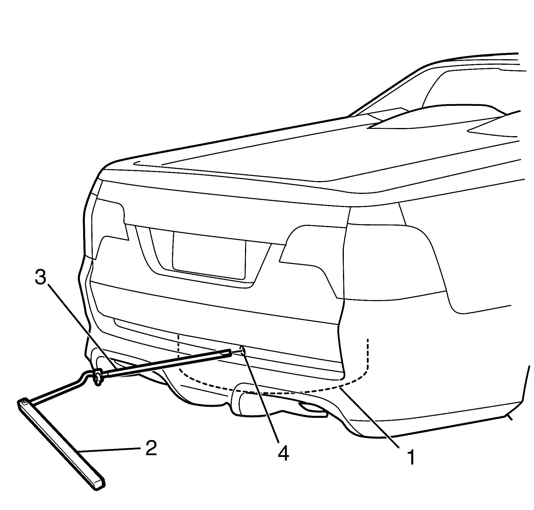
Important: Ensure the vehicle is located on flat ground, the park brake is applied, and the front wheels chocked to prevent vehicle movement.
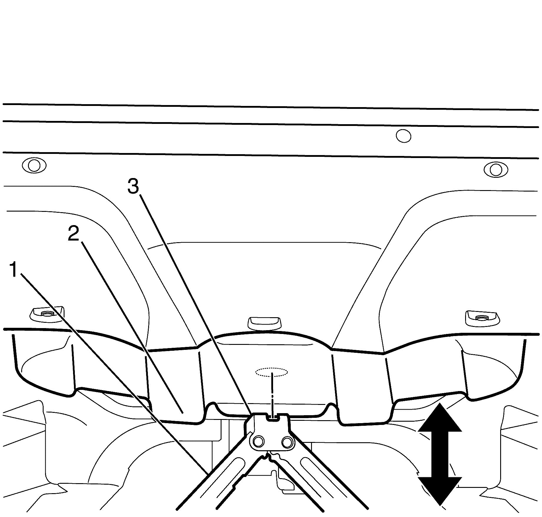
Important: The jack head must contact the spare wheel carrier as close to the centre as is possible. to prevent the spare wheel carrier from falling off the jack while it is being raised.
Important: Do not continue to raise the jack once the spare wheel carrier has stopped moving as this may cause the rear of the vehicle to lift off the ground and therefore become unstable.
Important: While the spare wheel carrier is lowering continue to ensure it lowers horizontally. If the spare wheel carrier lowers on an angle, proceed with caution.
Spare Wheel Carrier Winch Inoperative
Spare Wheel Carrier Winch Secondary Latch System
This vehicle has an underbody mounted spare wheel carrier and winch assembly, equipped with a secondary latch system. The secondary latch is designed to stop the spare wheel from suddenly falling off the vehicle if the winch mounted cable securing the spare wheel is damaged.
Secondary Latch Operation
Correct spare tyre secondary latch operation requires the spare tyre to be stored with the inflation valve directed downwards into the spare wheel carrier.
If the spare wheel winch is inoperative the secondary latch must be released.
Installation Procedure
- Install the tire carrier (2) to the vehicle.
- Install the tire carrier to spare tire carrier support retaining bolts (1).
- Install the spare wheel (1) into the spare wheel carrier (2).
- Engage the retainer plate (3) onto the locating studs (4).
- Install the circlip (5), through the retainer plate (3) to secure the spare wheel (1) into the spare wheel carrier (2).
- Using suitable vehicle specific tools, raise the spare wheel carrier (1) into the stowed position in the vehicle body (2) .
- Lower the vehicle. Refer to Lifting and Jacking the Vehicle .

Notice: Refer to Fastener Notice in the Preface section.
Tighten
Tighten the bolts to 22 N·m (16 lb ft).
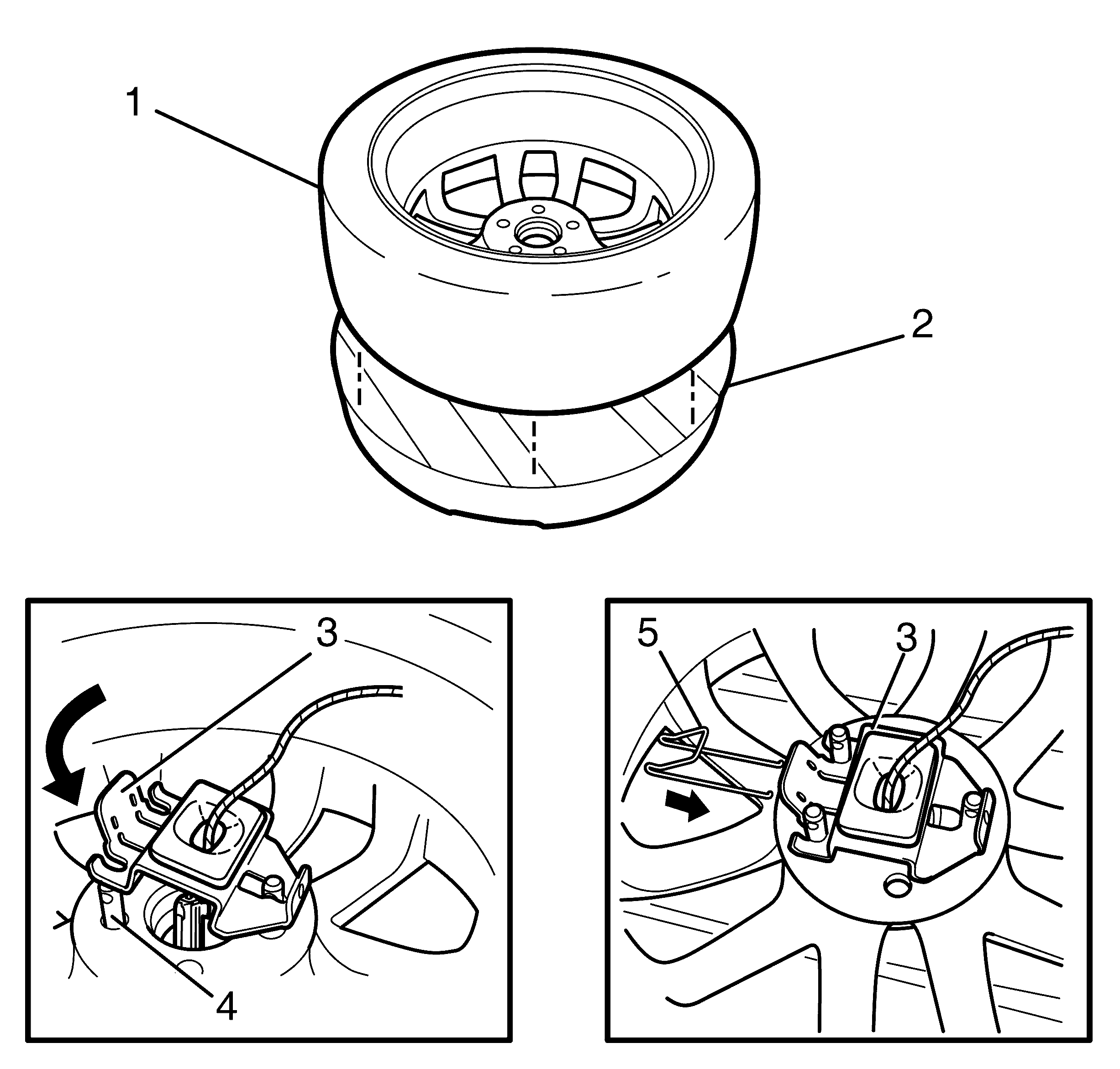
Important: For correct installation, the spare wheel must installed face down in the spare wheel carrier, with the inflation valve facing the ground, and be correctly aligned on the locating studs inside the spare wheel carrier.

