Tools Required
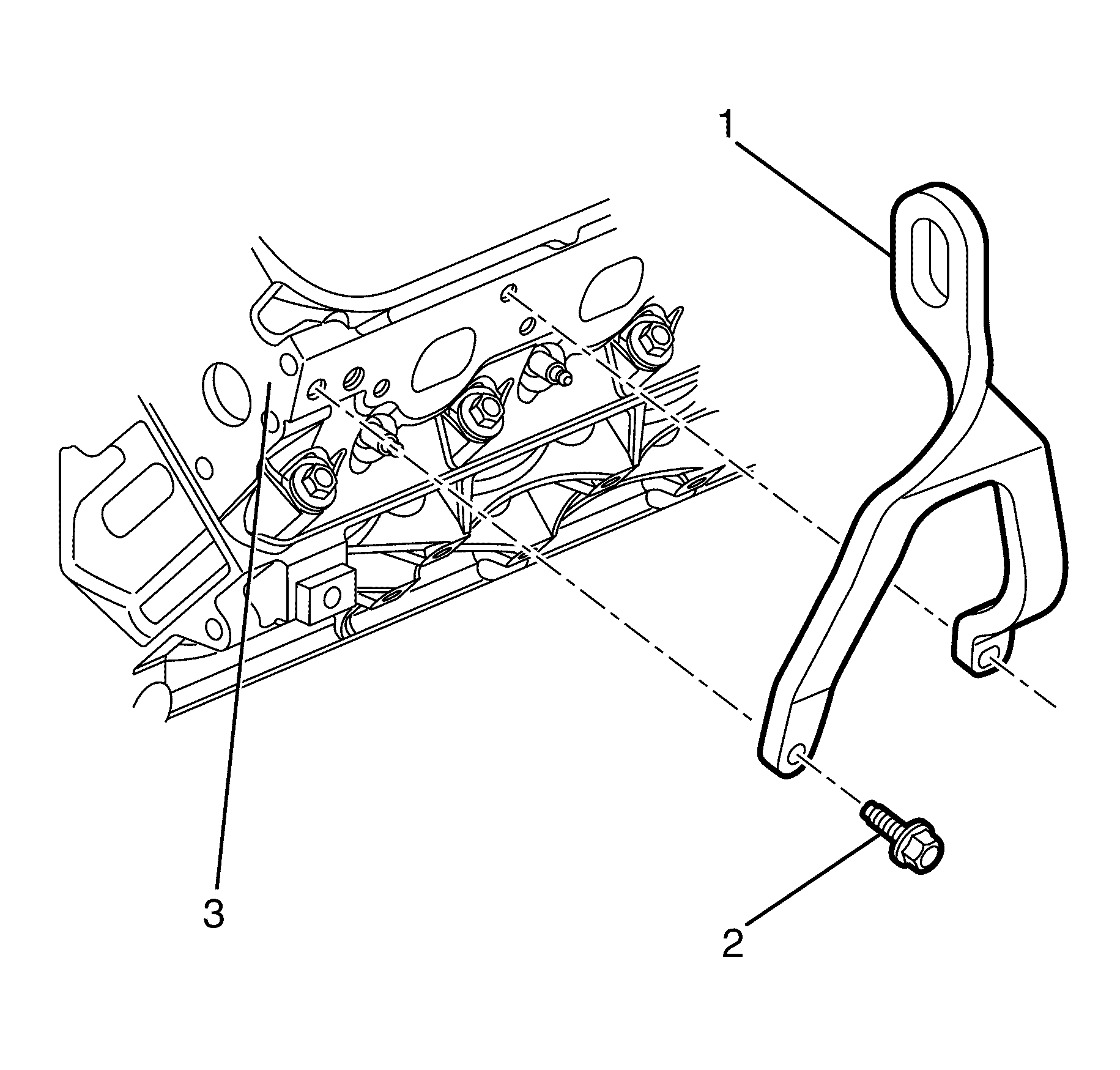
EN 46114 Engine Lift Bracket
Removal Procedure
- Remove the engine dress cover. Refer to Engine Cover Replacement for 3.6L engine or Engine Cover Replacement for 6.0L engine.
- Remove the radiator air baffle. Refer to Radiator Air Upper Baffle and Deflector Replacement .
- Position the EN 46114 (1) on the cylinder head (2).
- Install the EN 46114 to cylinder head retaining bolts (3).
- Install a suitable lifting tool and raise the engine assembly until the engine mount brackets (1) are clear of the engine mount retainers (2).
- Raise and support the vehicle. Refer to Lifting and Jacking the Vehicle.
- Remove the front bumper fascia. Refer to Front Bumper Fascia Replacement.
- Remove the front air deflector. Refer to Front Air Deflector Replacement.
- Remove the splash shield. Refer to Engine Splash Shield Replacement.
- Remove the front control arm. Refer to Control Arm Replacement.
- Remove the front castor arm. Refer to Front Lower Control Front Arm Replacement.
- Remove the stabilizer shaft link. Refer to Stabilizer Shaft Link Replacement.
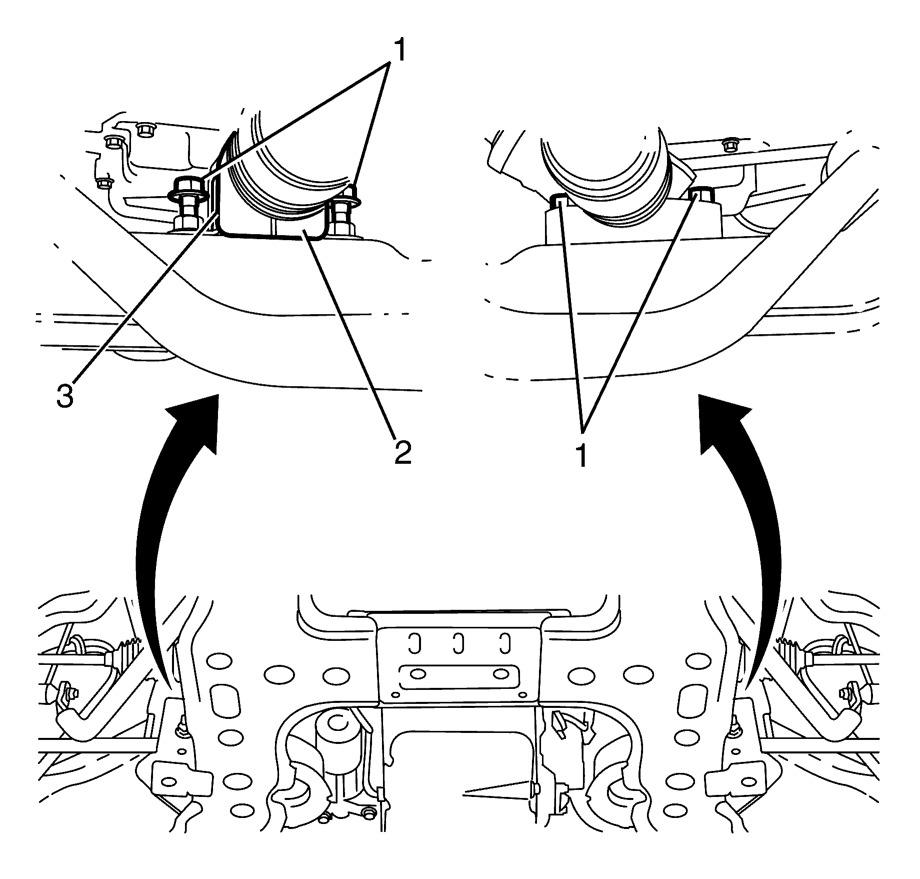
- Remove the steering gear to subframe retaining bolts (1).
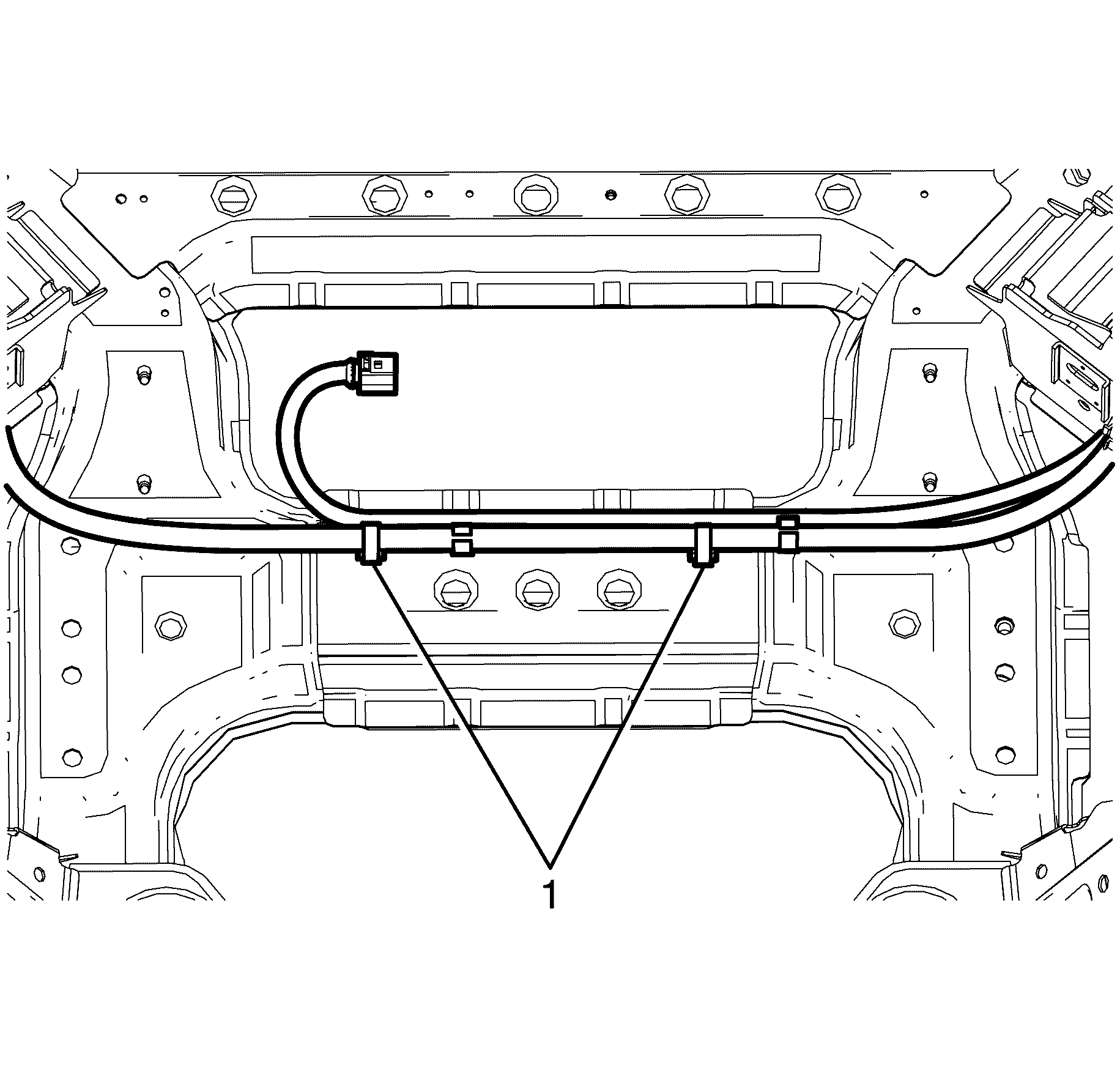
- Disconnect the electrical harness retainers (1) securing the engine harness to the frame.
- Secure the radiator to the radiator upper mounting brackets.
- Install a suitable bench trolley under the frame.
- Lower the vehicle to the frame support table.
- Remove the front sub frame to front chassis rail retaining bolts (2).
- Carefully raise the body from the frame.
- Make sure when raising the body the following items are clear from the frame.
- Remove the lower engine mount to front sub frame retaining nuts (1).
- Remove the stabliser bar insulator bracket to subframe retaining nuts (3) on both sides of the stabiliser bar (4). Repeat for the opposite side.
- Remove the stabliser bar insulator bracket (2) from the subframe (1) on both sides of the stabiliser bar.
- Remove the stabliser bar from the front subframe.
- With the aid of an assistant, remove the frame from the support fixture.
Caution: Refer to Safety Glasses Caution in the Preface section.
Caution: Refer to Vehicle Lifting Caution in the Preface section.
Notice: Refer to Fastener Notice in the Preface section.
Tighten
Tighten the
EN 46114
to cylinder head retaining bolts (3) to 50 N·m (36 lb ft).
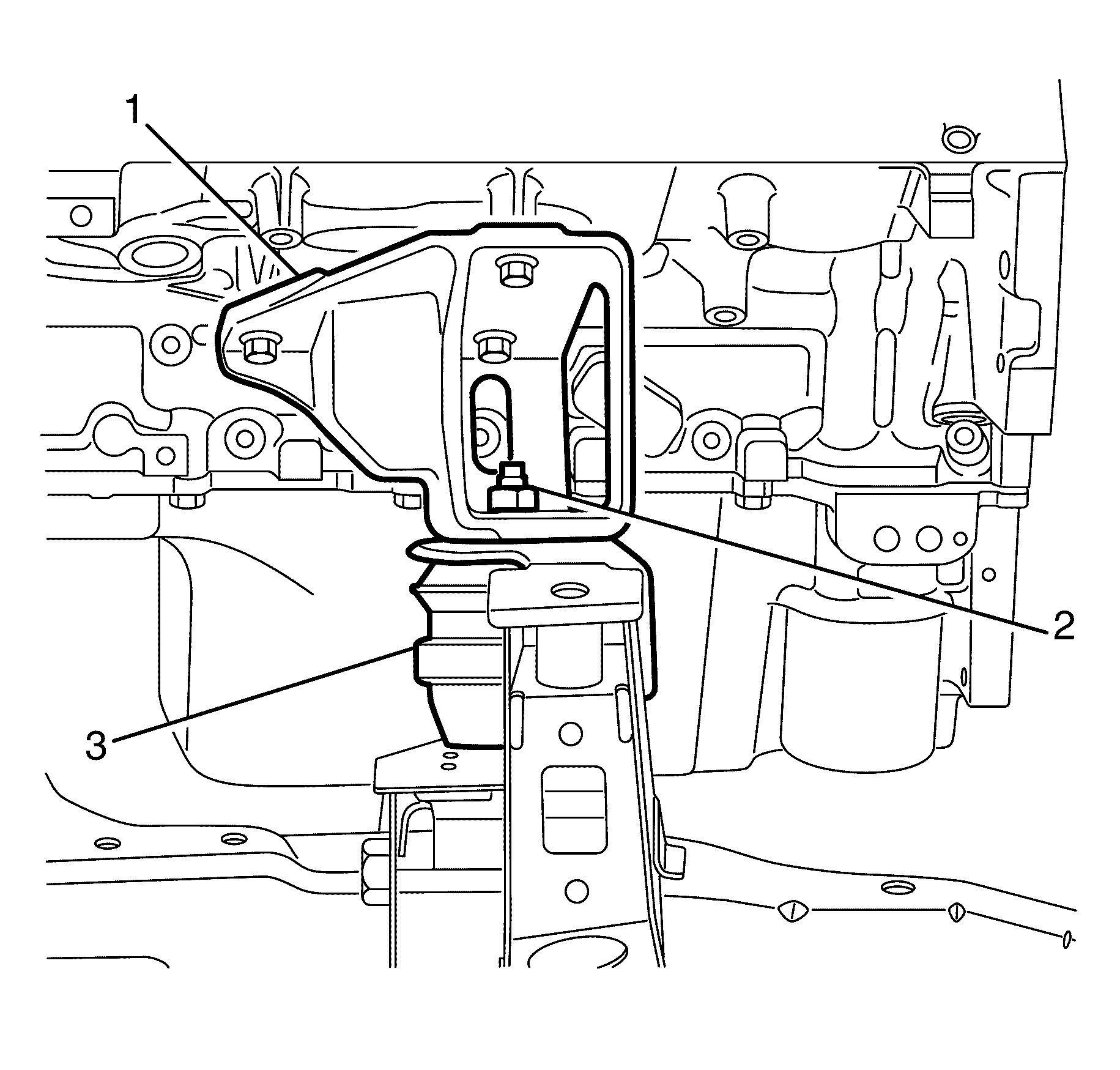
Important: When lifting the engine assembly, observe the clearance between the rear of the engine assembly and the dash panel.
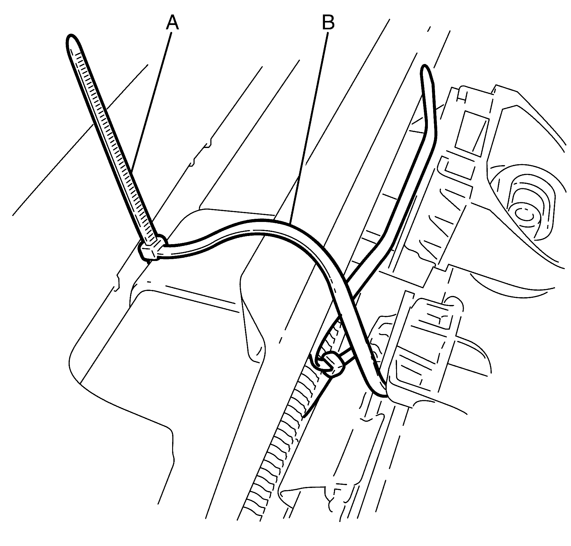
Important: It is necessary to secure the radiator to the front end assembly, as the radiator is supported by the subframe.
Important: Thread zip tie A around the front end assembly and zip tie B through the radiator and condenser mount. Insert zip tie A into the retainer of zip tie B and insert zip tie B into the retainer of zip tie A.
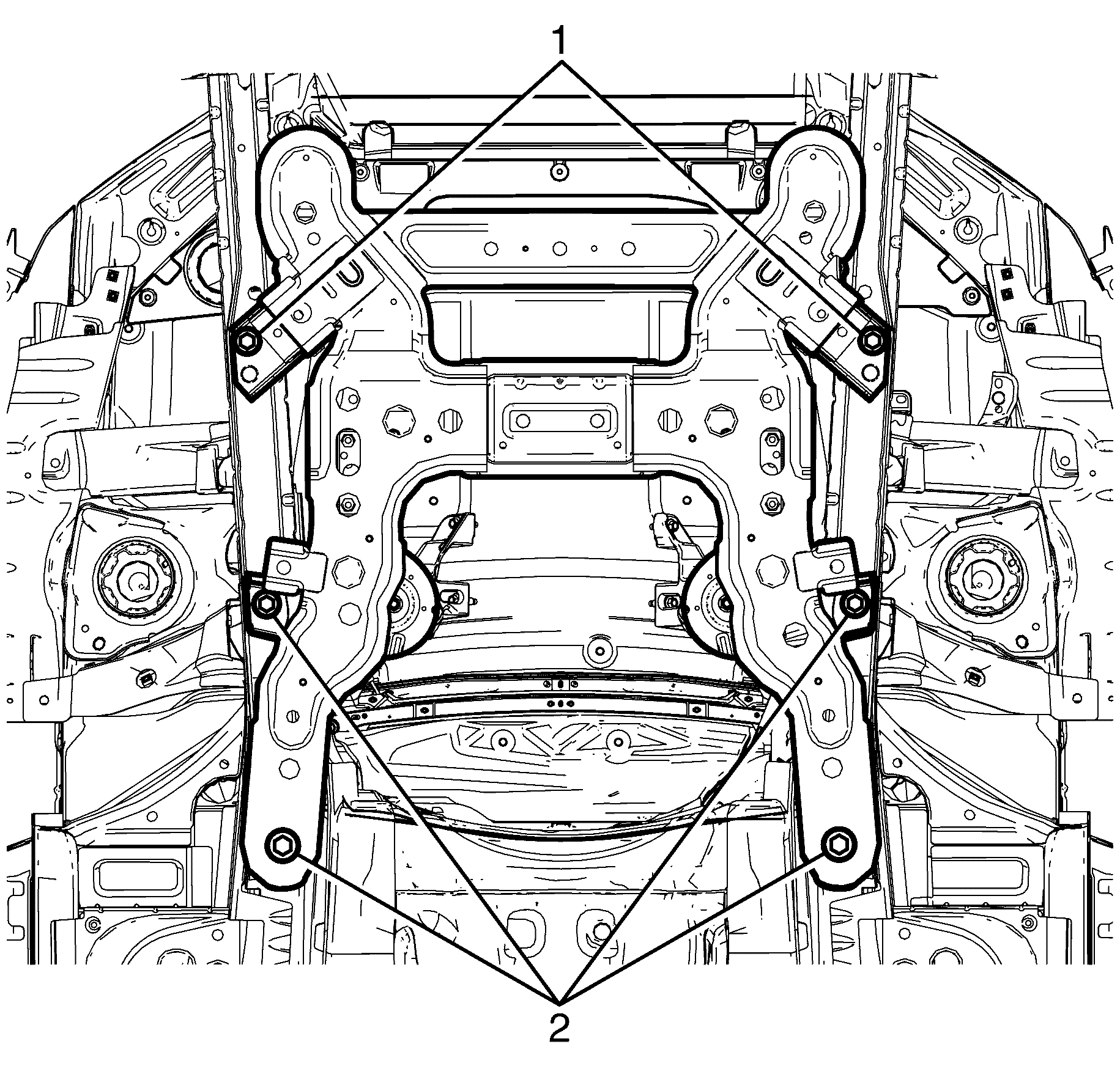
| • | The brake pipes |
| • | The steering knuckle assembly |
| • | The wheel speed sensor electrical harness |
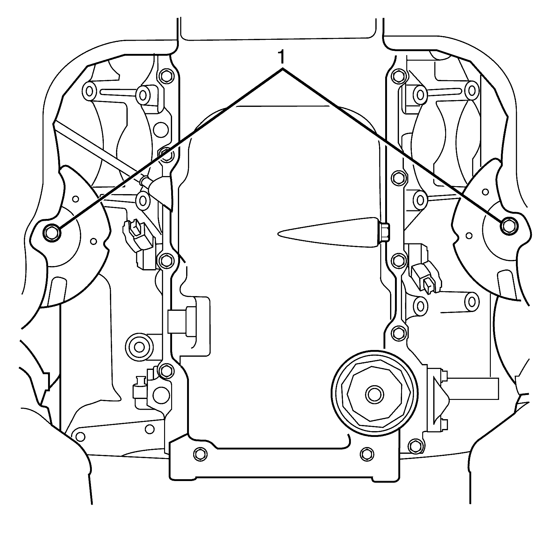
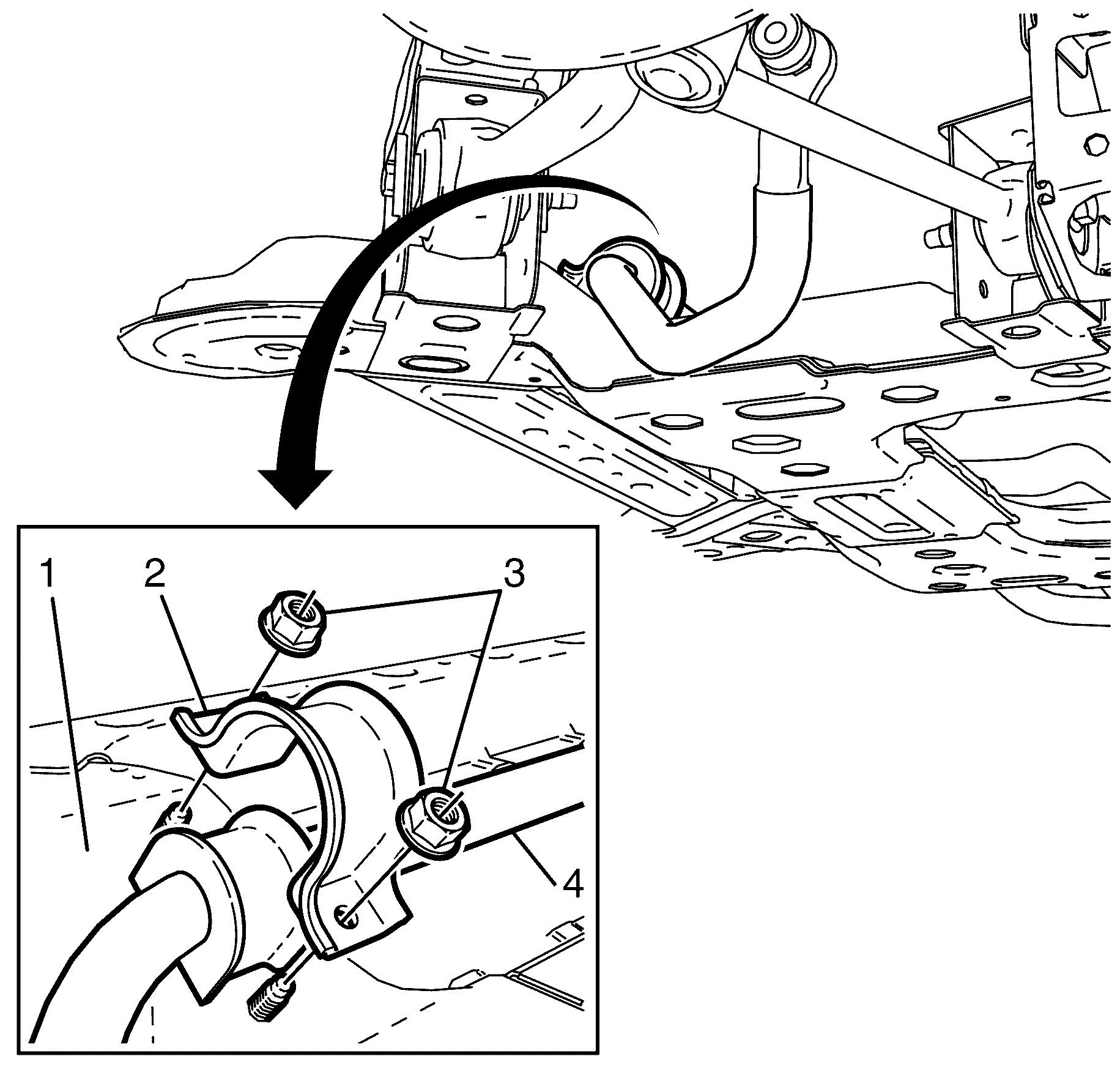
Important: Nuts with micro-encapsulated thread sealant must be discarded after removal.
Discard the nuts.
Installation Procedure
- With the aid of an assistant, install the frame to the support fixture.
- Install the stabilizer bar to the front subframe.
- install the stabilizer bar caps (2) to the front subframe
- Install NEW stabilizer shaft to front sub frame retaining nuts (3).
- Install the engine mount to the front subframe.
- Install the lower engine mount to front sub frame retaining nuts (2).
- Carefully lower the body to the frame.
- Make sure the following components are clear from the frame.
- Install the front sub frame to front chassis rail retaining bolts (1 and 2).
- Raise the vehicle.
- Remove the suitable bench trolley from under the vehicle.
- Lower the engine and remove the suitable lifting tool from the engine.
- Install the lower engine mount to front sub frame retaining nuts (2).
- Cut zip tie A around the front end assembly and zip tie B through the radiator and condenser mount.
- Secure the engine electrical harness retainers (1) to the frame.
- Install the steering gear insulator (3) to the steering gear.
- Install the steering gear insulator retaining bracket (2) to the steering gear insulator (3).
- Install the steering gear to subframe retaining bolts (1).
- Install the stabilizer shaft link. Refer to Stabilizer Shaft Link Replacement.
- Install the front castor arm. Refer to Front Lower Control Front Arm Replacement.
- Install the front control arm. Refer to Control Arm Replacement.
- Install the splash shield. Refer to Engine Splash Shield Replacement.
- Install the front air deflector. Refer to Front Air Deflector Replacement.
- Install the front bumper fascia. Refer to Front Bumper Fascia Replacement.
- Lower the suitable lifting tool until the engine mount brackets are located on the engine mount retainers.
- Remove the EN 46114 to cylinder head retaining bolts (3).
- Remove the EN 46114 (1) from the cylinder head (2).
- Install the radiator air baffle. Refer to Radiator Air Upper Baffle and Deflector Replacement
- Install the engine dress cover. Refer to Engine Cover Replacement for 3.6L engine or Engine Cover Replacement for 6.0L engine.
- Align the vehicle. Refer to Wheel Alignment Measurement .

Important: Do not fully tighten the stabilizer shaft retaining bolts to the frame at this stage.
Do not fully tighten at this stage.
Do not fully tighten at this stage.
| • | The wheel speed sensor electrical harness |
| • | The steering knuckle assembly |
| • | The brake pipes |
Notice: Refer to Fastener Notice in the Preface section.

Tighten
Tighten the bolts to 95 N·m (70 lb ft).

Tighten
Tighten the retaining nuts to 80 N·m
(59 lb ft).


Notice: Refer to Fastener Notice in the Preface section.
Tighten
Tighten the retaining bolts to 65 N·m
(48 lb ft).

Important: When lifting the engine assembly, observe the clearance between the rear of the engine assembly and the dash panel.
Notice: Refer to Fastener Notice in the Preface section.

