Steering Gear Replacement 3.6L Engine RHD
Tools Required
CH-49405 Ball Joint Release Too.l
Removal Procedure
- Remove the engine dress cover. Refer to Engine Cover Replacement.
- Remove the air inlet duct. Refer to Air Cleaner Inlet Duct Replacement.
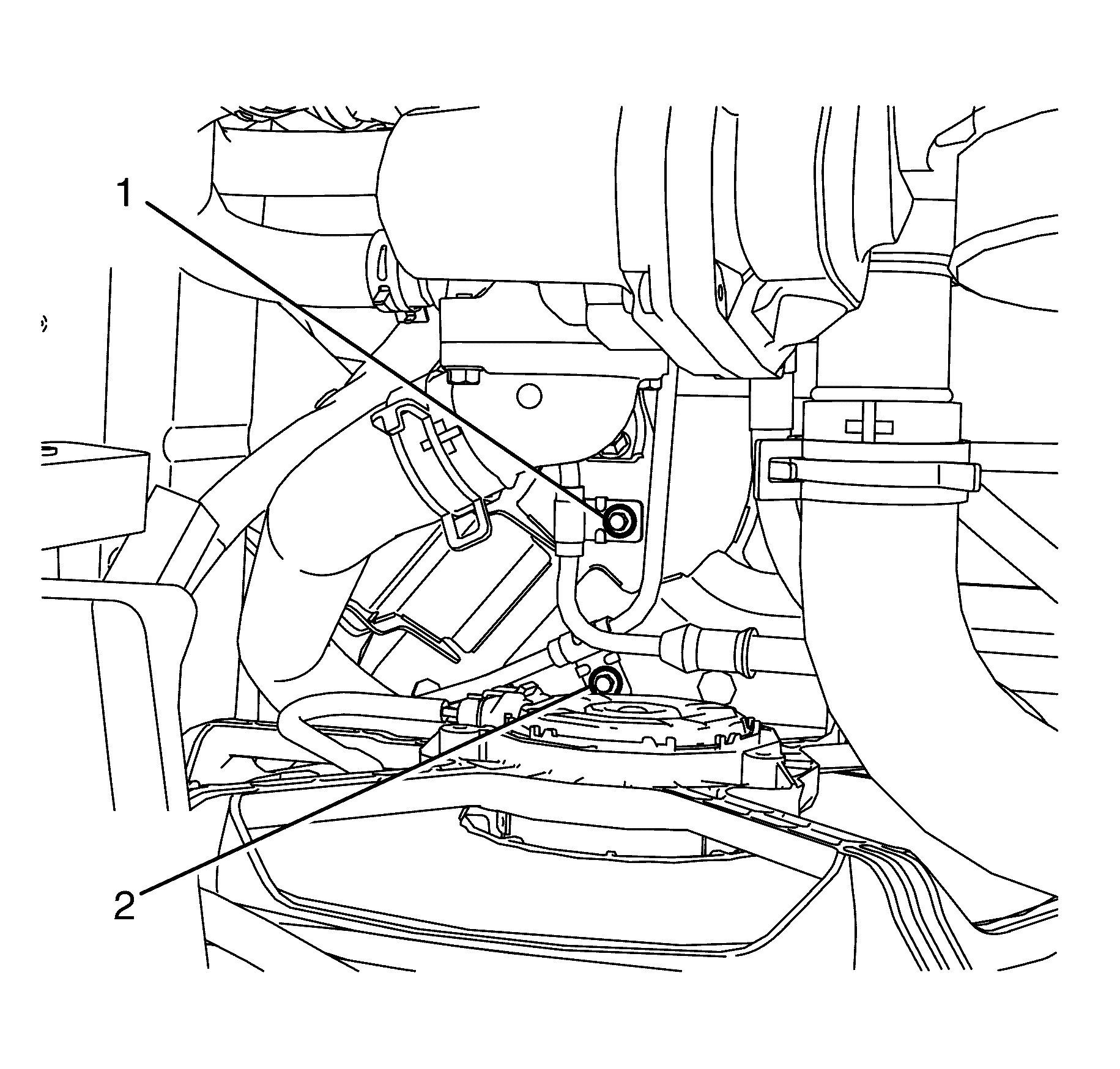
- Remove the power steering gear inlet pipe/hose bracket to subframe retaining bolt (1).
- Remove the power steering gear outlet pipe/hose bracket to subframe retaining bolt (2).
- Raise and support the vehicle. Refer to Lifting and Jacking the Vehicle.
- Remove the front wheels. Refer to Tire and Wheel Removal and Installation.
- Loosen the tie rod end lock nut (2) half a turn.
- Remove the tie rod end to steering knuckle retaining nut (4).
- Separate the tie rod end (3) from the steering knuckle (2) using the CH-49405 (1).
- Remove the CH-49405 (1).
- Disconnect the tie rod end (3) from the steering knuckle (1).
- Remove the tie rod end (3) from the tie rod (4).
- Repeat steps 6 to 11 on the other side of the vehicle.
- Remove the engine undertray. Refer to.
- Mark the intermediate steering shaft (1) in relation to the pinion shaft (3).
- Remove the intermediate steering shaft to pinion shaft retaining bolt (2).
- Disconnect the intermediate shaft (2) from the pinion shaft (3).
- Lower the vehicle.
- Remove the driver side front castor arm to steering knuckle retaining nut (1).
- Separate the driver side front castor arm (3) from the steering knuckle (1) using the CH-49405 (2).
- Disconnect the driver side front castor arm (3) from the steering knuckle (1).
- Place a large suitable container under the vehicle in order to collect draining fluid.
- Remove the power steering gear inlet pipe/hose to power steering gear retaining banjo bolt (2) and copper sealing washers (1).
- Remove the power steering gear outlet pipe/hose to power steering gear retaining banjo bolt (3) and copper sealing washers (4).
- Remove the steering gear to subframe retaining bolts (1).
- Remove the steering gear insulator retaining bracket (2) from the steering gear insulator (3).
- Remove the steering gear insulator (3) from the steering gear.
- Remove the steering gear from the vehicle.
Caution: Refer to Safety Glasses Caution in the Preface section.
Caution: Refer to Vehicle Lifting Caution in the Preface section.
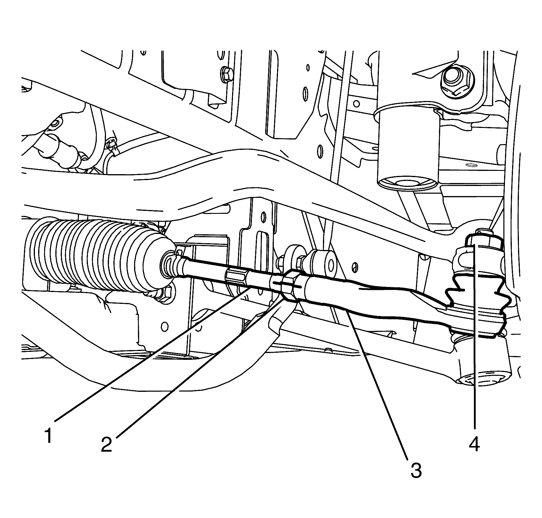
Important: Mark the tie rod end (3) and tie rod end lock nut (2) in relation to the tie rod (1).
Important: Nuts with micro-encapsulated thread sealant must be discarded after removal.
Discard the nut.
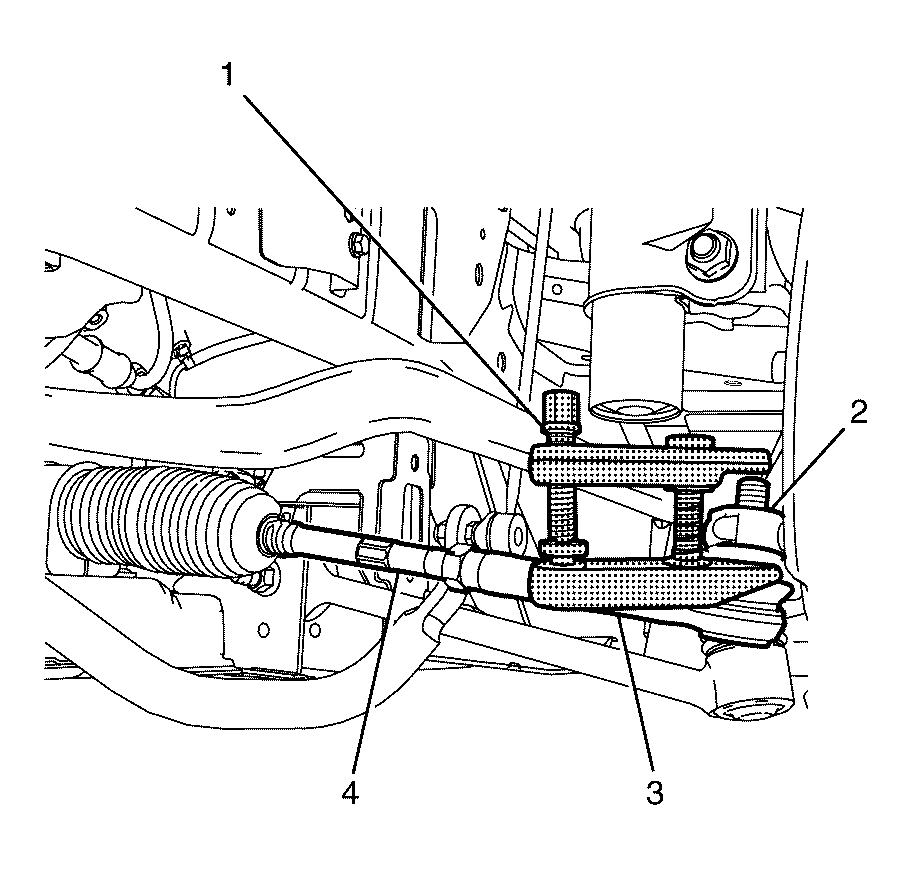
Important: Once a load is applied by the ball joint release tool loading bolt, a quick tap on the nut end of the tool will reduce the separating force required.
Important: Note the number of turns required to remove.
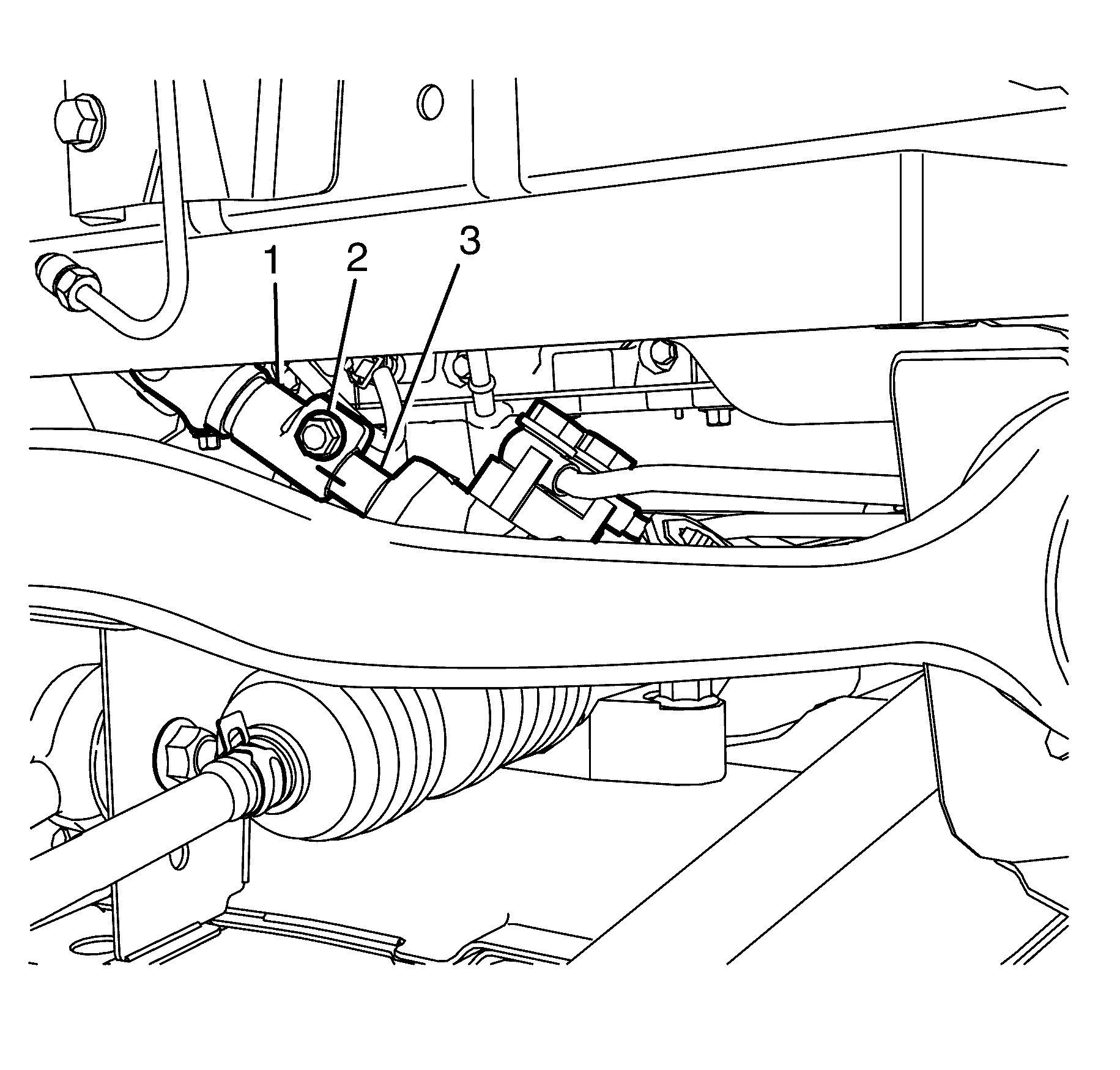
Important: Observing the orientation of the intermediate steering shaft (1) with reference to the pinion shaft (3) will minimise the potential of incorrect steering column assembly alignment.
Important: Bolts with micro-encapsulated thread sealant must be discarded after removal.
Discard the bolt.
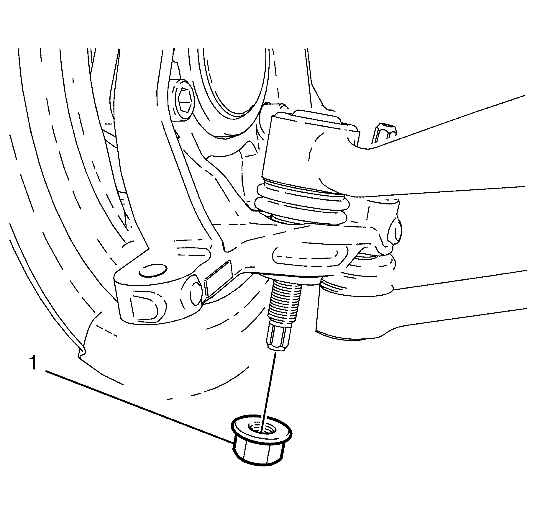
Important: Nuts with micro-encapsulated thread sealant must be discarded after removal.
Discard the nut.
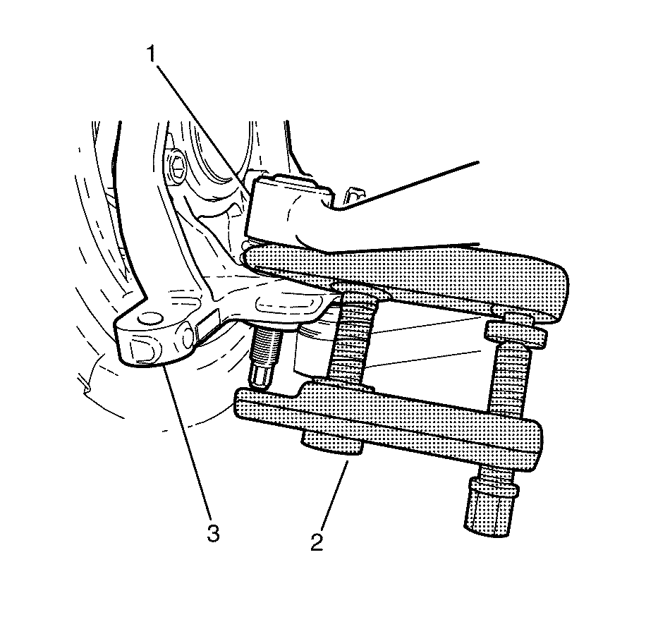
Important: Once a load is applied by the release tool loading bolt, a quick tap on the nut end of the tool will reduce the separating force required.
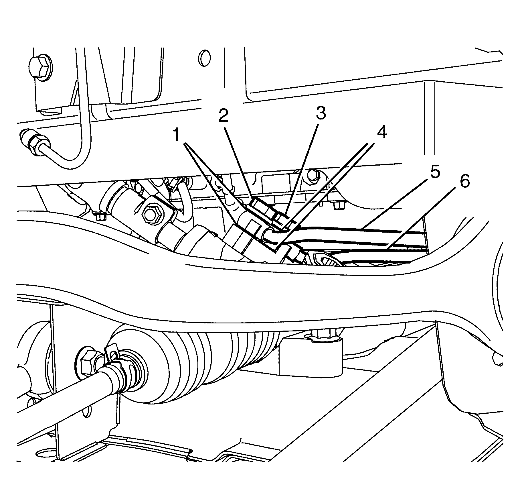
Important: The power steering inlet pipe/hose (5) must be plugged to prevent the entry of foreign particles into the power steering system.
Important: The copper sealing washers (1) must be discarded after removal.
Plug the steering gear inlet pipe/hose (5).
Discard the washers.
Important: The power steering outlet pipe/hose (6) must be plugged to prevent the entry of foreign particles into the power steering system.
Important: The copper sealing washers (4) must be discarded after removal.
Plug the steering gear outlet pipe/hose (6).
Discard the washers.
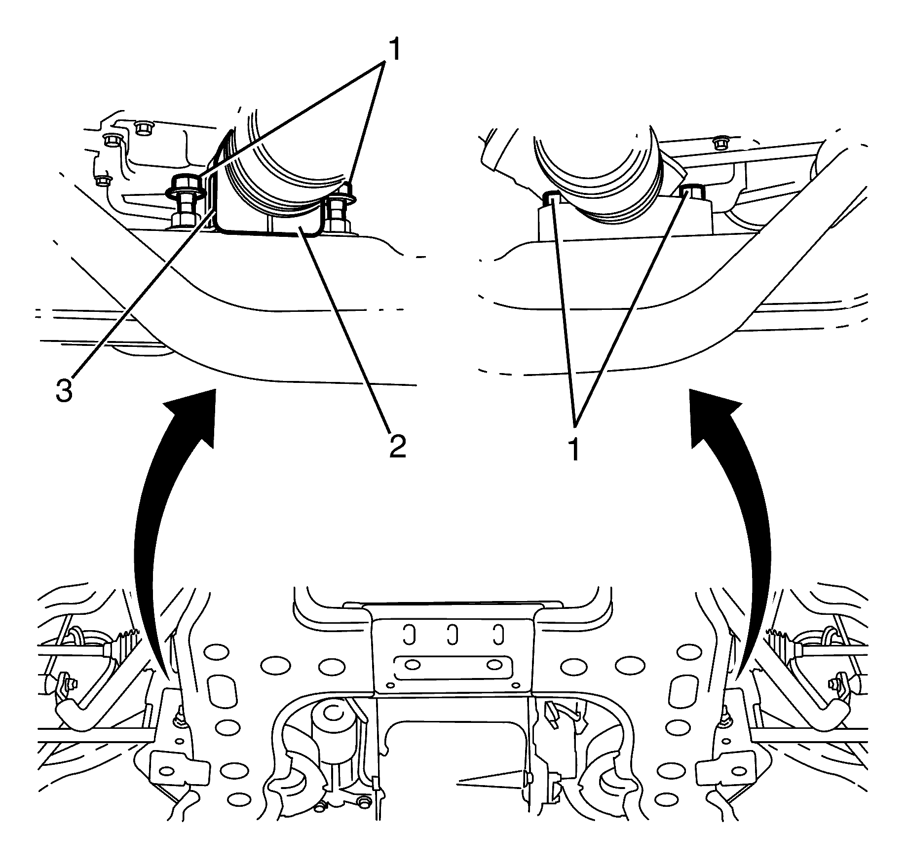
Important: The steering gear must be removed from the driver side of the vehicle.
Installation Procedure
- Install the steering gear to the vehicle.
- Install the steering gear insulator (3) to the steering gear.
- Install the steering gear insulator retaining bracket (2) to the steering gear insulator (3).
- Install the steering gear to subframe retaining bolts (1).
- Remove the plug from the steering gear inlet pipe/hose (5).
- Install the power steering gear inlet pipe/hose to power steering gear retaining banjo bolt (1) and NEW copper sealing washers (2).
- Remove the plug from the steering gear outlet pipe/hose (6).
- Install the power steering gear outlet pipe/hose to power steering gear retaining banjo bolt (3) and NEW copper sealing washers (4).
- Remove the container from under the vehicle.
- Connect the driver side front castor arm (2) to the steering knuckle (1).
- Install the driver side front castor arm ball joint to steering knuckle NEW retaining nut (3).
- Connect the intermediate steering shaft (1) to the pinion shaft (3).
- Install the intermediate steering shaft to pinion shaft NEW retaining bolt (2).
- Install the tie rod end (3) to the tie rod (1).
- Connect the tie rod end (3) to the steering knuckle (4).
- Install the tie rod end to steering knuckle retaining NEW nut (5).
- Repeat steps 14 to 16 on the other side of the vehicle.
- Install the engine undertray. Refer to Engine Splash Shield Replacement.
- Install the front wheels. Refer to Tire and Wheel Removal and Installation.
- Remove the safety stands.
- Lower the vehicle to the ground.
- Install the power steering gear inlet pipe/hose bracket to subframe retaining bolt (1).
- Install the power steering gear outlet pipe/hose bracket to subframe retaining bolt (2).
- Fill power steering fluid reservoir with fluid to the MAX level mark on the reservoir.
- Bleed the power steering system. Refer to Power Steering System Bleeding.
- Check for power steering fluid leaks.
- Install the engine dress cover. Refer to Engine Cover Replacement.
- Install the air inlet duct. Refer to Air Cleaner Inlet Duct Replacement.
- Bounce the vehicle several times to settle the suspension.
- Check and adjust the wheel alignment. Refer to Wheel Alignment Measurement.
- Tighten the tie rod end lock nut (1).

Important: The steering gear must be installed from the driver side of the vehicle.
Notice: Refer to Fastener Notice in the Preface section.
Tighten
Tighten the Bolts to 65 N·m (48 lb ft).

Tighten
Tighten the banjo bolt to 58 N·m (42 lb ft).
Tighten
Tighten the banjo bolt to 58 N·m (43 lb ft).
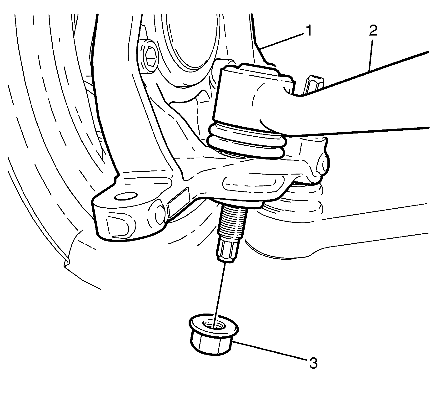
Tighten
Tighten nut to 70 N·m (52 lb ft).

Important: The intermediate steering shaft and pinion shaft splines must be installed in the position recorded during removal and aligned with the marks previously made.
Tighten
Tighten the bolt to 25 N·m (18 lb ft).
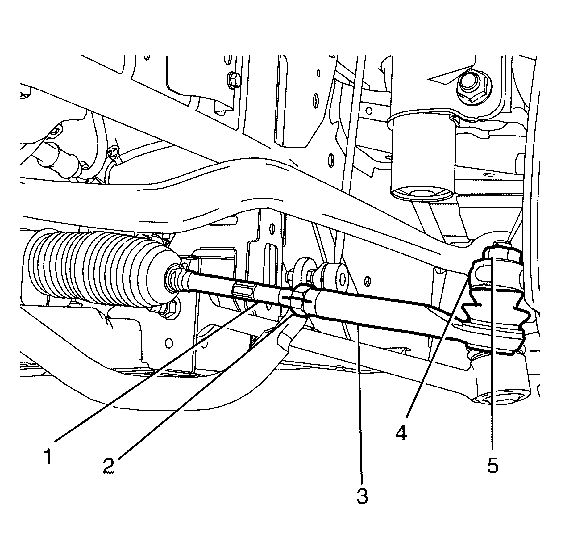
Important: The tie rod end (3) must be installed rotating the same number of turns as recorded during removal and aligned with the mark previously made on the tie rod (1) and tie rod end lock nut (2).
Tighten
Tighten the nut to 25 N·m+ 120 degrees
(18 lb ft + 120 degrees).

Tighten
Tighten the bolt to 9 N·m (80 lb in).
Tighten
Tighten the bolt to 9 N·m (80 lb in).
Notice: When adding fluid or making a complete fluid change, always use the proper power steering fluid. Failure to use the proper fluid will cause hose and seal damage and fluid leaks.
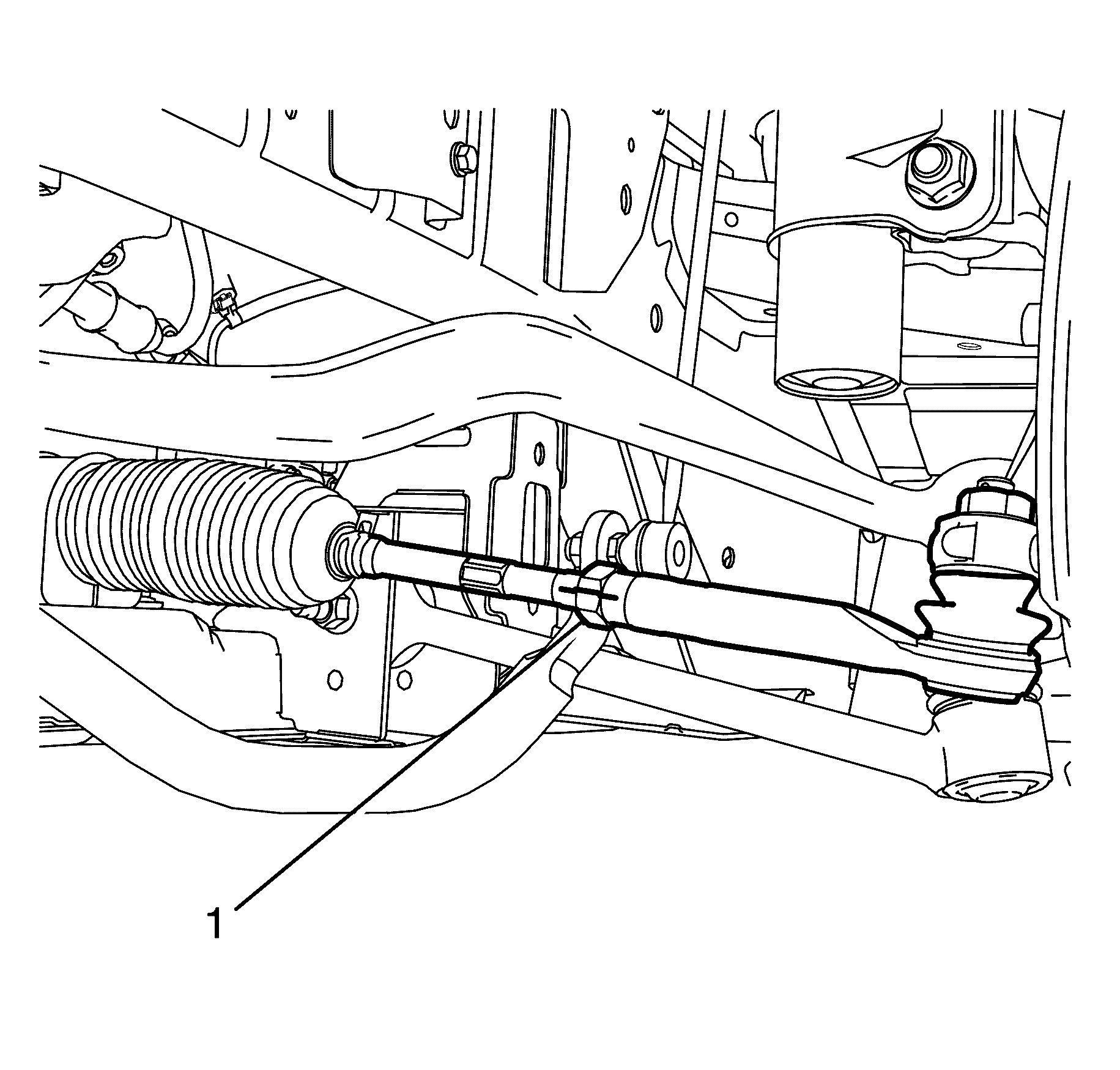
Tighten
Tighten the nut to 50 N·m (37 lb ft).
Steering Gear Replacement 6.0L Engine RHD
Tools Required
6297 Ball Joint Release Too.l
Removal Procedure
- Remove the engine dress cover. Refer to Engine Cover Replacement.
- Remove the air inlet duct. Refer to Air Cleaner Assembly Replacement.
- Remove the power steering gear inlet pipe/hose bracket to subframe retaining bolt (1).
- Remove the power steering gear outlet pipe/hose bracket to subframe retaining bolt (2).
- Raise and support the vehicle. Refer to Lifting and Jacking the Vehicle.
- Remove the front wheels. Refer to Tire and Wheel Removal and Installation.
- Loosen the tie rod end lock nut (2) half a turn.
- Remove the tie rod end to steering knuckle retaining nut (4).
- Separate the tie rod end (3) from the steering knuckle (2) using the 6297 (1).
- Remove the 6297 (1).
- Disconnect the tie rod end (3) from the steering knuckle (1).
- Remove the tie rod end (3) from the tie rod (4).
- Repeat steps 6 to 11 on the other side of the vehicle.
- Remove the engine undertray. Refer to Engine Splash Shield Replacement.
- Mark the intermediate steering shaft (1) in relation to the pinion shaft (3).
- Remove the intermediate steering shaft to pinion shaft retaining bolt (2).
- Disconnect the intermediate shaft (2) from the pinion shaft (3).
- Lower the vehicle.
- Remove the driver side front castor arm to steering knuckle retaining nut (1).
- Separate the driver side front castor arm (3) from the steering knuckle (1) using the 6297 (2).
- Disconnect the driver side front castor arm (3) from the steering knuckle (1).
- Place a large suitable container under the vehicle in order to collect draining fluid.
- Remove the power steering gear inlet pipe/hose to power steering gear retaining banjo bolt (2) and copper sealing washers (1).
- Remove the power steering gear outlet pipe/hose to power steering gear retaining banjo bolt (3) and copper sealing washers (4).
- Remove the steering gear to subframe retaining bolts (1).
- Remove the steering gear insulator retaining bracket (2) from the steering gear insulator (3).
- Remove the steering gear insulator (3) from the steering gear.
- Remove the steering gear from the vehicle.
Caution: Refer to Safety Glasses Caution in the Preface section.
Caution: Refer to Vehicle Lifting Caution in the Preface section.


Important: Mark the tie rod end (3) and tie rod end lock nut (2) in relation to the tie rod (1).
Important: Nuts with micro-encapsulated thread sealant must be discarded after removal.
Discard the nut.

Important: Once a load is applied by the ball joint release tool loading bolt, a quick tap on the nut end of the tool will reduce the separating force required.
Important: Note the number of turns required to remove.

Important: Observing the orientation of the intermediate steering shaft (1) with reference to the pinion shaft (3) will minimise the potential of incorrect steering column assembly alignment.
Important: Bolts with micro-encapsulated thread sealant must be discarded after removal.
Discard the bolt.

Important: Nuts with micro-encapsulated thread sealant must be discarded after removal.
Discard the nut.

Important: Once a load is applied by the release tool loading bolt, a quick tap on the nut end of the tool will reduce the separating force required.

Important: The power steering inlet pipe/hose (5) must be plugged to prevent the entry of foreign particles into the power steering system.
Important: The copper sealing washers (1) must be discarded after removal.
Plug the steering gear inlet pipe/hose (5).
Discard the washers.
Important: The power steering outlet pipe/hose (6) must be plugged to prevent the entry of foreign particles into the power steering system.
Important: The copper sealing washers (4) must be discarded after removal.
Plug the steering gear outlet pipe/hose (6).
Discard the washers.

Important: The steering gear must be removed from the driver side of the vehicle.
Installation Procedure
- Install the steering gear to the vehicle.
- Install the steering gear insulator (3) to the steering gear.
- Install the steering gear insulator retaining bracket (2) to the steering gear insulator (3).
- Install the steering gear to subframe retaining bolts (1).
- Remove the plug from the steering gear inlet pipe/hose (5).
- Install the power steering gear inlet pipe/hose to power steering gear retaining banjo bolt (1) and NEW copper sealing washers (2).
- Remove the plug from the steering gear outlet pipe/hose (6).
- Install the power steering gear outlet pipe/hose to power steering gear retaining banjo bolt (3) and NEW copper sealing washers (4).
- Remove the container from under the vehicle.
- Install the driver side front control arm (2) to the steering knuckle (1).
- Install the driver side front castor arm ball joint to steering knuckle NEW retaining nut (3).
- Connect the intermediate steering shaft (1) to the pinion shaft (3).
- Install the intermediate steering shaft to pinion shaft NEW retaining bolt (2).
- Install the tie rod end (3) to the tie rod (1).
- Connect the tie rod end (3) to the steering knuckle (4).
- Install the tie rod end to steering knuckle retaining NEW nut (5).
- Repeat steps 14 to 16 on the other side of the vehicle.
- Install the engine undertray. Refer to Engine Splash Shield Replacement.
- Install the front wheels. Refer to Tire and Wheel Removal and Installation.
- Remove the safety stands.
- Lower the vehicle to the ground.
- Install the power steering gear inlet pipe/hose bracket to subframe retaining bolt (1).
- Install the power steering gear outlet pipe/hose bracket to subframe retaining bolt (2).
- Fill power steering fluid reservoir with fluid to the MAX level mark on the reservoir.
- Bleed the power steering system. Refer to Power Steering System Bleeding.
- Check for power steering fluid leaks.
- Install the engine dress cover. Refer to Engine Cover Replacement.
- Install the air inlet duct. Refer to Air Cleaner Assembly Replacement3.
- Bounce the vehicle several times to settle the suspension.
- Check and adjust the wheel alignment. Refer to Wheel Alignment Measurement.
- Tighten the tie rod end lock nut (1).

Important: The steering gear must be installed from the driver side of the vehicle.
Notice: Refer to Fastener Notice in the Preface section.
Tighten
Tighten the Bolts to 65 N·m (48 lb ft).

Tighten
Tighten the banjo bolt to 58 N·m (43 lb ft).
Tighten
Tighten the banjo bolt to 58 N·m (43 lb ft).

Tighten
Tighten nut to 70 N·m (52 lb ft).

Important: The intermediate steering shaft and pinion shaft splines must be installed in the position recorded during removal and aligned with the marks previously made.
Tighten
Tighten the bolt to 25 N·m (18 lb ft).

Important: The tie rod end (3) must be installed rotating the same number of turns as recorded during removal and aligned with the mark previously made on the tie rod (1) and tie rod end lock nut (2).
Tighten
Tighten the nut to 25 N·m+ 120 degrees
(18 lb ft + 120 degrees).

Tighten
Tighten the bolt to 9 N·m (80 lb in).
Tighten
Tighten the bolt to 9 N·m (80 lb in).
Notice: When adding fluid or making a complete fluid change, always use the proper power steering fluid. Failure to use the proper fluid will cause hose and seal damage and fluid leaks.

Tighten
Tighten the nut to 50 N·m (37 lb ft).
