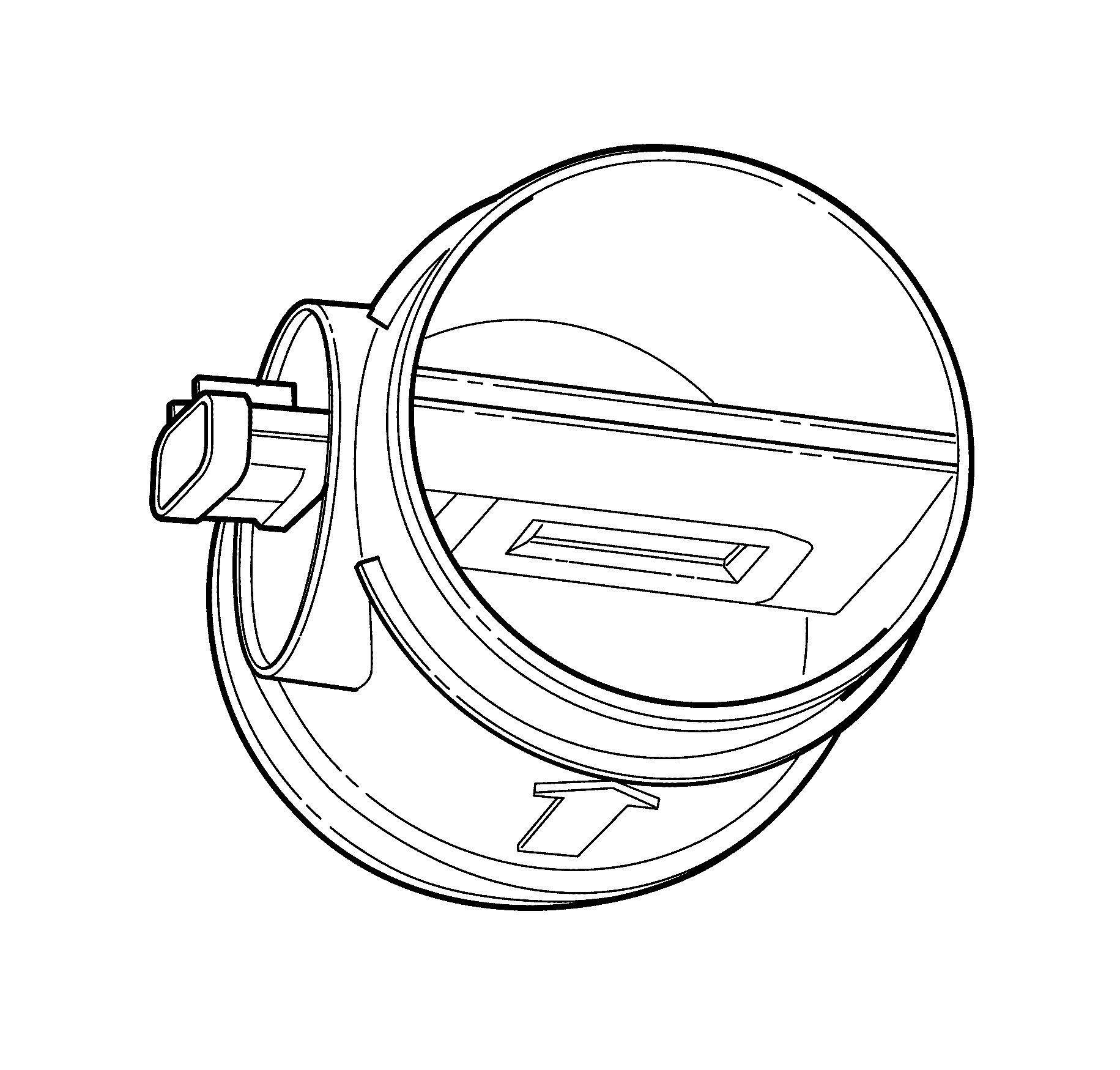
Mass Air Flow Sensor

The MAF sensor measures the amount of air coming into the engine. This direct
airflow measurement is more accurate than the calculated airflow information obtained
from the other sensor inputs. The MAF sensor also houses an integrated intake air
temperature (IAT) sensor. The MAF sensor uses the following circuits:
| • | An ignition 1 voltage circuit |
| • | A 5-volt reference circuit |
| • | A low reference circuit |
The MAF sensor that is used on this vehicle measures the air flow rate. The
MAF output voltage is a function of the power required to keep the air flow sensing
elements at a fixed temperature above the ambient temperature. The air flowing through
the sensor cools the sensing elements. The amount of cooling is proportional to the
amount of air flow. As the air flow increases, more current is needed in order to
maintain the hot film at a constant temperature. The MAF sensor converts the changes
in the current draw to a voltage signal that the ECM monitors. The ECM calculates
the air flow based on this signal.
The ECM monitors the MAF sensor signal voltage and can determine if the sensor
signal voltage is too low or too high. The ECM can also detect airflow that is inappropriate
for a given operating condition based on the signal voltage.
The scan tool displays the MAF value and displays the value in grams per second
(g/s). Values should change rather quickly on acceleration, but should remain fairly
stable at any given engine speed. If the ECM detects a condition with the MAF sensor
circuits, the following DTCs set:
| • | P0101 Mass Air Flow (MAF) Sensor Performance |
| • | P0102 Mass Air Flow (MAF) Sensor Circuit Low Voltage |
| • | P0103 Mass Air Flow (MAF) Sensor Circuit High Voltage |

