Entertainment/Communication Connector End Views SWBLHD
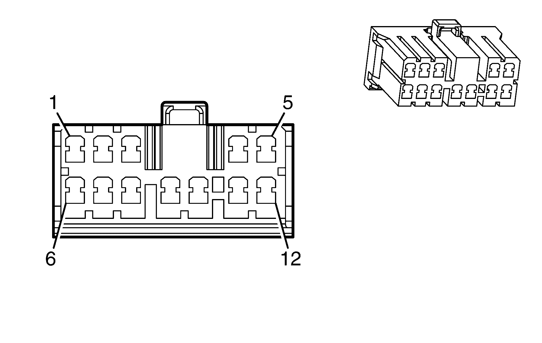
| |||
|---|---|---|---|
Connector Part Information | |||
Pin | Wire Colour | Wire Size | Function |
1 | BN | 0.5 | Left Rear Speaker Output (+) |
2 | D-BU | 0.5 | Right Rear Speaker Output (+) |
3 | D-BU/WH | 1.0 | Left or Rear Subwoofer Speaker Output (+) |
4 | RD/WH | 2.0 | Battery Positive Voltage |
5 | BK | XX | Ground |
6 | YE | 0.5 | Left Rear Speaker Output (-) |
7 | L-BU | 0.5 | Right Rear Speaker Output (-) |
8 | L-GN/BK | 1.0 | [Left or Rear] Subwoofer Speaker Output (-) |
9 | D-GN | 1.0 | Right Subwoofer Speaker Output (+) |
10 | L-BU/BK | 1.0 | Right Subwoofer Speaker Output (-) |
11 | RD/WH | 2.0 | Battery Positive Voltage |
12 | BK | XX | Ground |
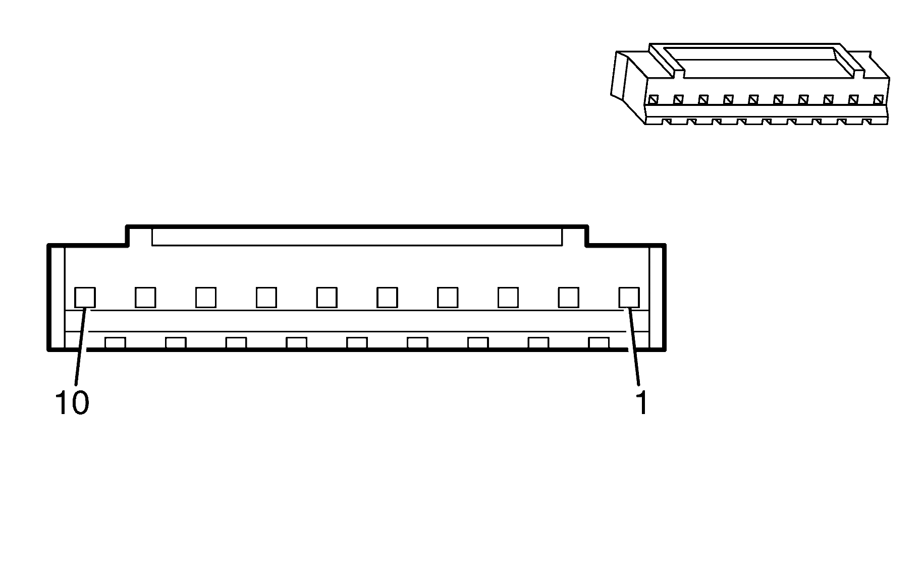
| |||
|---|---|---|---|
Connector Part Information | |||
Pin | Wire Colour | Wire Size | Function |
X1-1 | GY | 0.32 | ?? |
X1-2 | YE/BK | 0.32 | ?? |
X1-3 | -- | -- | -- |
X1-4 | NO COLOUR | -- | Drain Wire |
X1-5 | L-BU | 0.3 | DVD Audio Left Signal (+) |
X1-6 | WH/BK | 0.32 | DVD Audio Left Signal (-) |
X1-7 | WH | 0.3 | DVD Audio Right Signal (+) |
X1-8 | D-GN | 0.3 | DVD Audio Right Signal (-) |
X1-9 | GY | 0.3 | DVD Video Signal (-) |
X1-10 | D-GN | 0.32 | DVD Video Signal (+) |
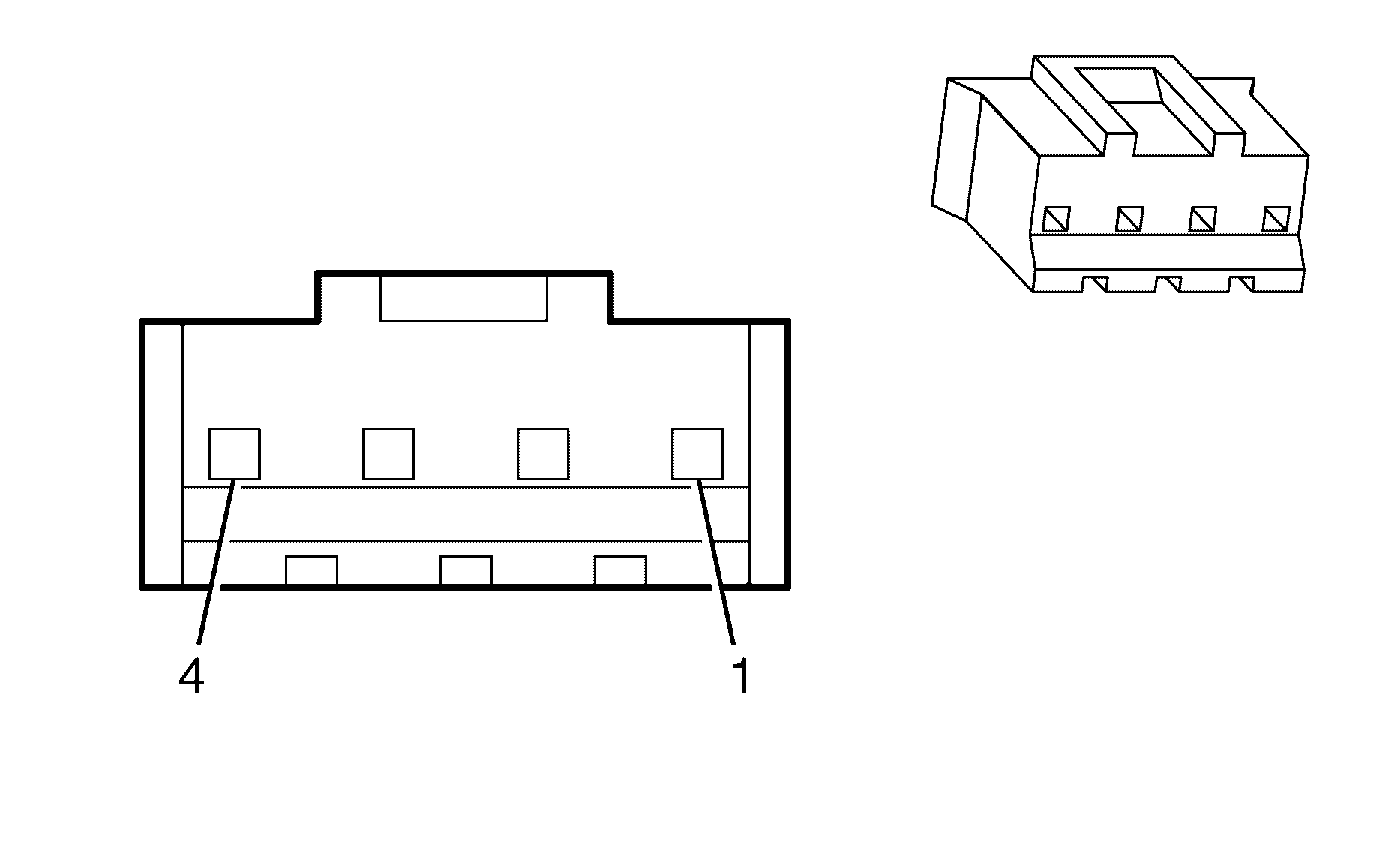
| |||
|---|---|---|---|
Connector Part Information | |||
Pin | Wire Colour | Wire Size | Function |
X2-1 | XX | XX | XX |
X2-2 | XX | XX | XX |
X2-3 | XX | XX | XX |
X2-4 | XX | XX | XX |
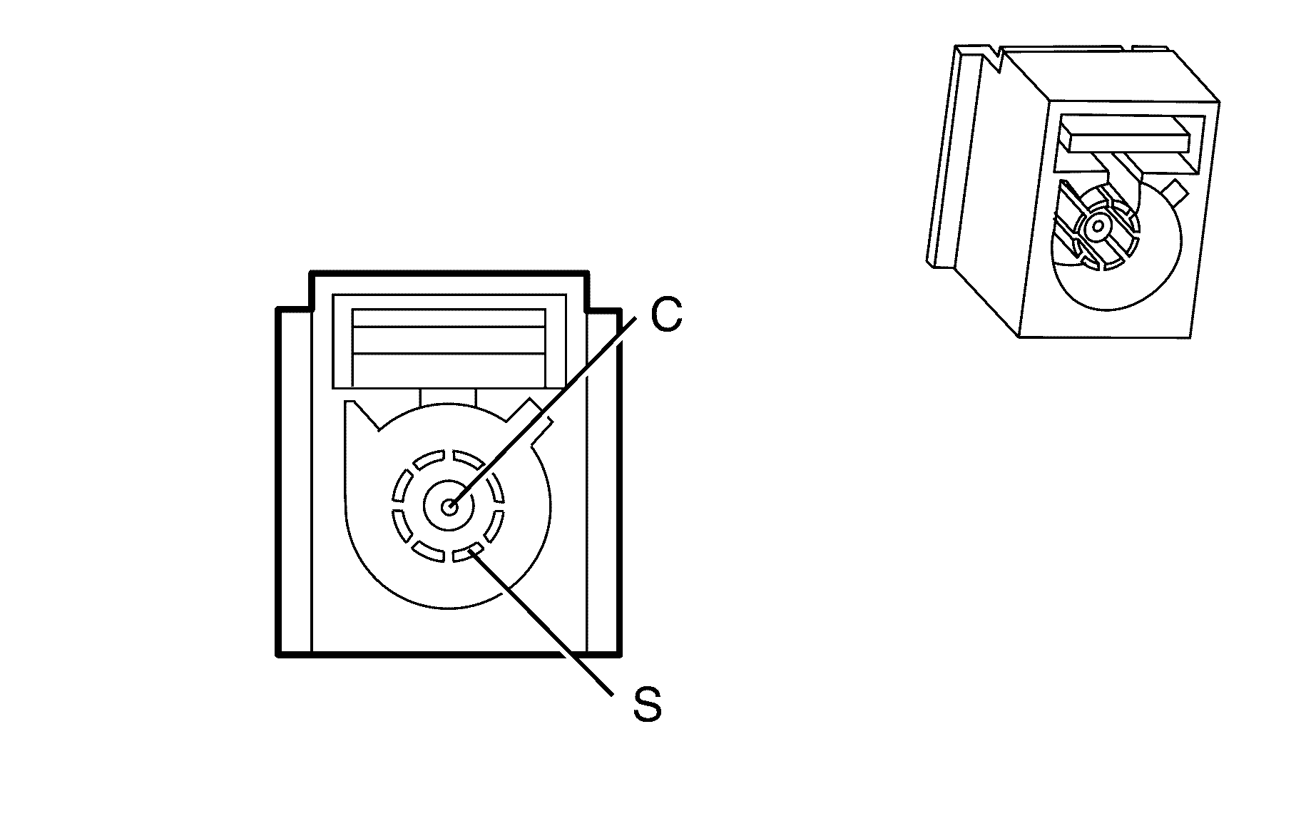
| |||
|---|---|---|---|
Connector Part Information | |||
Pin | Wire Colour | Wire Size | Function |
C | GY | 0.52 | Diversity Antenna Post |
S | Bare | 0.35 | Diversity Antenna Shield |
| |||
|---|---|---|---|
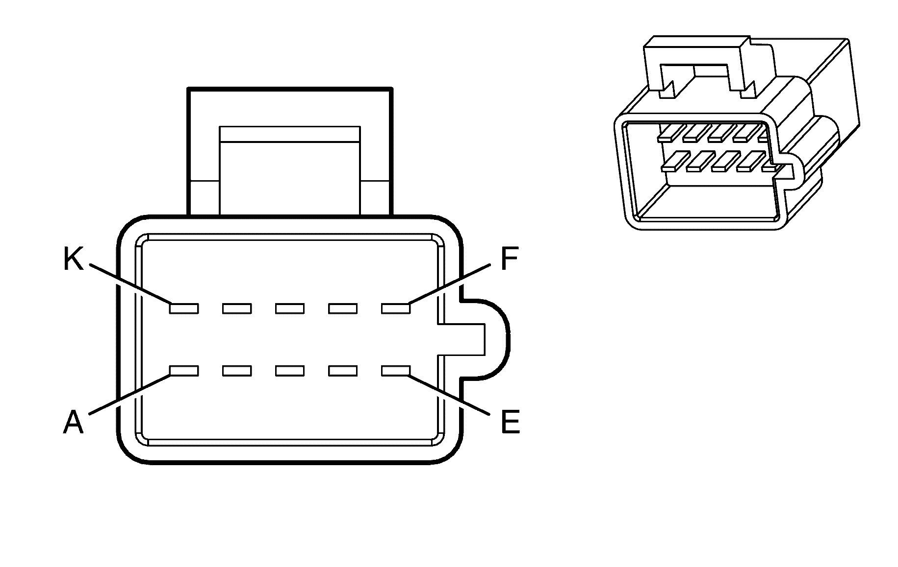
Connector Part Information | Male | ||
Pin | Wire Colour | Wire Size | Function |
X1-A | GY/BU | 0.3 | Steering Wheel Resistor Ladder Right Signal #2 |
X1-B | BN/GN | 0.3 | Steering Wheel Resistor Ladder Right Signal #1 |
X1-C | BN | 0.3 | Steering Wheel Resistor Ladder Left Signal #1 |
X1-D | L-BU | 0.3 | Steering Wheel Resistor Ladder Left Signal #2 |
X1-E | BN/WH | 0.3 | DIC Switch Low Reference |
X1-F | OG/BK | 0.3 | Steering Wheel Controls Signal |
X1-G | BK | 0.3 | Ground |
X1-H | PU/WH | 0.3 | I/P Dimming Control |
X1-I | -- | -- | -- |
X1-J | BN/BK | 0.3 | Horn Relay Control |
X1-K | -- | -- | -- |
| |||
|---|---|---|---|
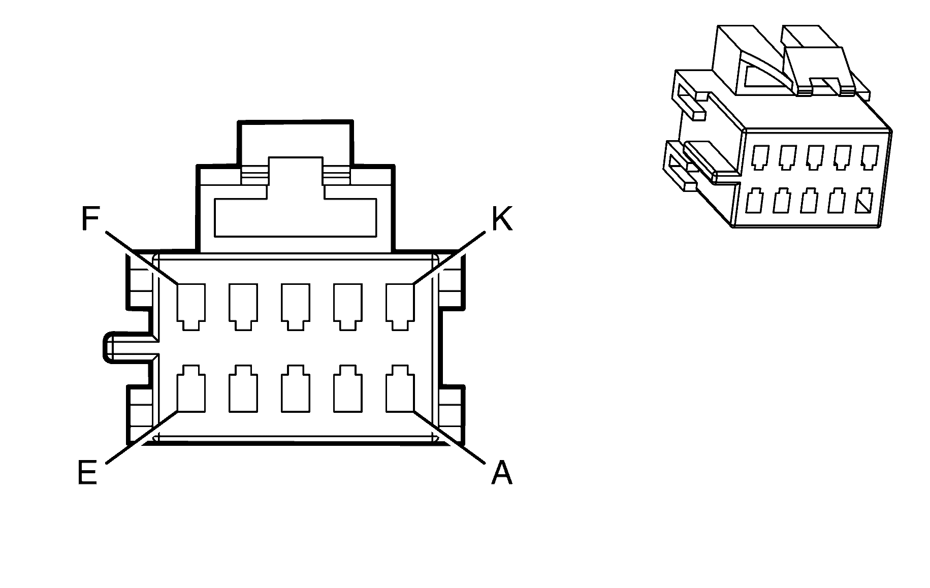
Connector Part Information | Female | ||
Pin | Wire Colour | Wire Size | Function |
X1-A | GY/BU | 0.3 | Steering Wheel Resistor Ladder Right Signal #2 |
X1-B | YE | 0.3 | Steering Wheel Resistor Ladder Right Signal #1 |
X1-C | BN | 0.3 | Steering Wheel Resistor Ladder Left Signal #1 |
X1-D | L-BU | 0.3 | Steering Wheel Resistor Ladder Left Signal #2 |
X1-E | GN | 0.3 | DIC Switch Low Reference |
X1-F | OG/BK | 0.3 | Steering Wheel Controls Signal |
X1-G | BK | 0.3 | Ground |
X1-H | PU | 0.3 | I/P Dimming Control |
X1-I | -- | 0.3 | -- |
X1-J | BK/WH | 0.3 | Horn Relay Control |
X1-K | -- | -- | -- |
| |||
|---|---|---|---|
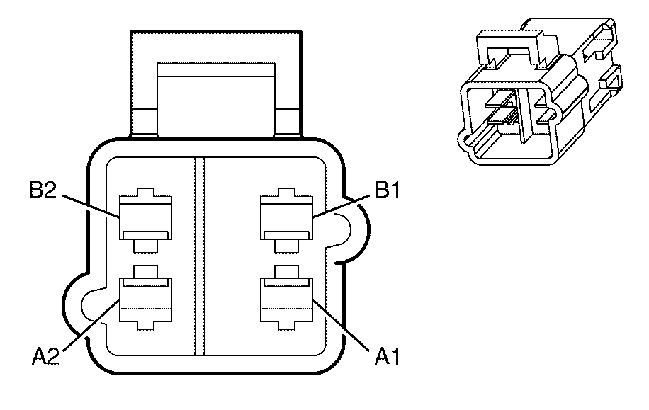
Connector Part Information | Male | ||
Pin | Wire Colour | Wire Size | Function |
A-1 | BN/RD | 0.3 | Steering Wheel Module - Stage1 - High Control |
A-2 | BN | 0.3 | Steering Wheel Module - Stage1 - Low Control |
B-1 | WH | 0.3 | Steering Wheel Module - Stage2 - High Control |
B-2 | PK | 0.3 | Steering Wheel Module - Stage2 - Low Control |
| |||
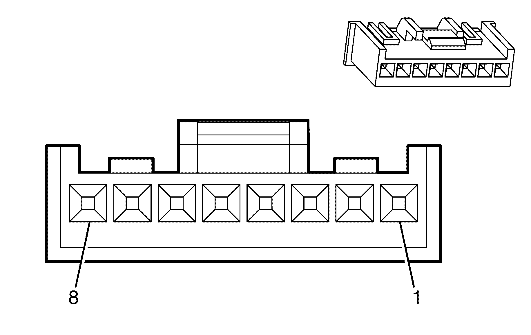
|---|---|---|---|
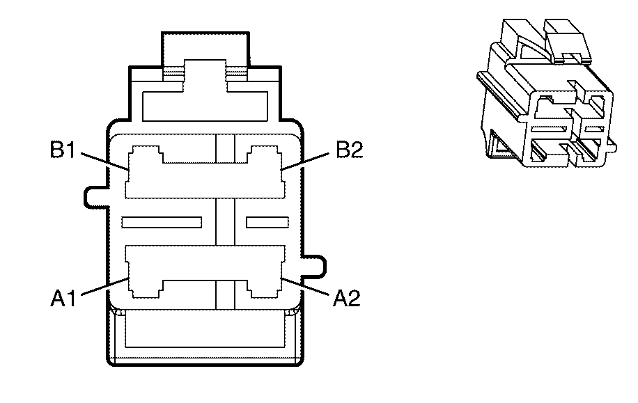
Connector Part Information | Female | ||
Pin | Wire Colour | Wire Size | Function |
A-1 | TN | 0.3 | Steering Wheel Module - Stage1 - High Control |
A-2 | BN | 0.3 | Steering Wheel Module - Stage1 - Low Control |
B-1 | WH | 0.3 | Steering Wheel Module - Stage2 - High Control |
B-2 | PK | 0.3 | Steering Wheel Module - Stage2 - Low Control |
| |||
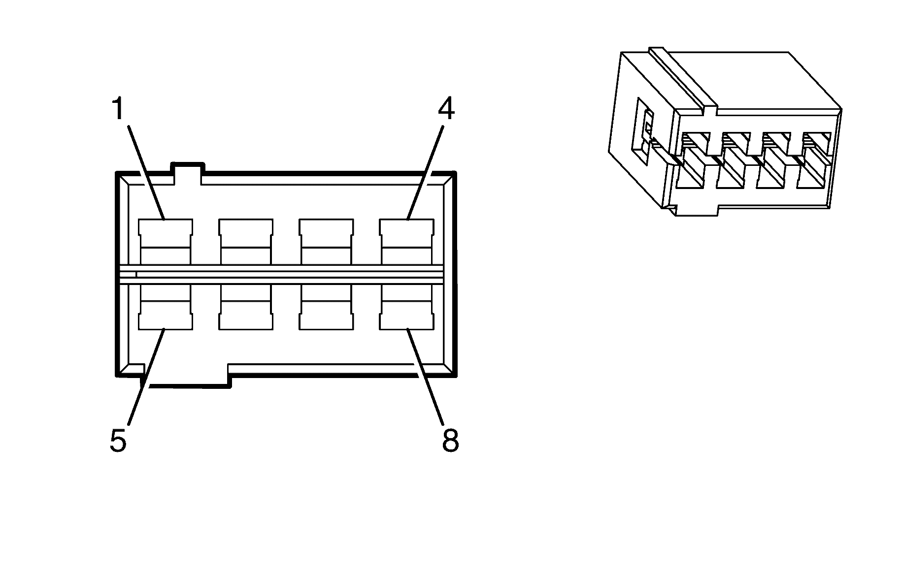
|---|---|---|---|
Connector Part Information | |||
Pin | Wire Colour | Wire Size | Function |
X2-1 | GY/BU | 0.3 | Steering Wheel Resistor Ladder Right Signal #2 |
X2-2 | YE | 0.3 | Steering Wheel Resistor Ladder Right Signal #1 |
X2-3 | BN | 0.3 | Steering Wheel Resistor Ladder Left Signal #1 |
X2-4 | L-BU | 0.3 | Steering Wheel Resistor Ladder Left Signal #2 |
X2-5 | GN | 0.3 | DIC Switch Low Reference |
X2-6 | OG/BK | 0.3 | Steering Wheel Controls Signal |
X2-7 | BK | 0.3 | Ground |
| |||
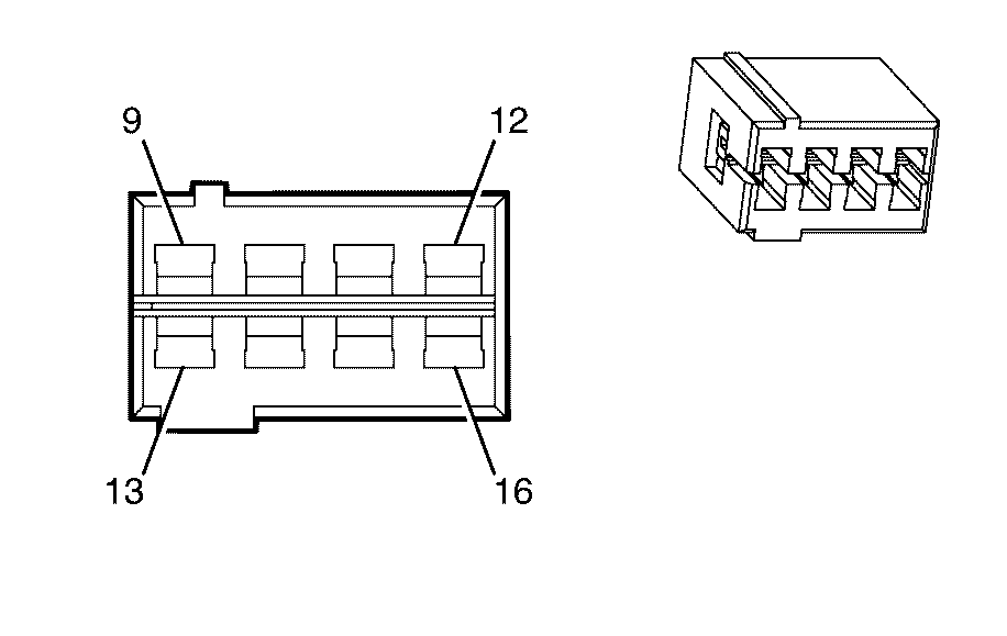
|---|---|---|---|
Connector Part Information | |||
Pin | Wire Colour | Wire Size | Function |
X1-1 | L-BU | 0.5 | Right Rear Speaker Output (-) |
X1-2 | D-GN | 0.5 | Right Front Speaker Output (-) |
X1-3 | GY | 0.5 | Left Front Speaker Output (-) |
X1-4 | YE | 0.5 | Left Rear Speaker Output (-) |
X1-5 | D-BU | 0.5 | Right Rear Speaker Output (+) |
X1-6 | L-GN | 0.5 | Right Front Speaker Output (+) |
X1-7 | TN | 0.5 | Left Front Speaker Output (+) |
X1-8 | BN | 0.5 | Left Rear Speaker Output (+) |
| |||
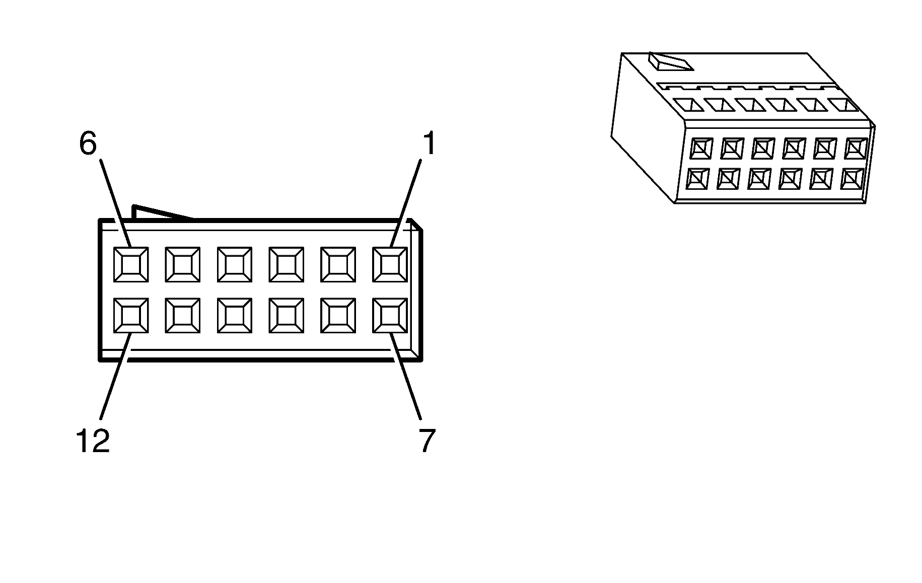
|---|---|---|---|
Connector Part Information | |||
Pin | Wire Colour | Wire Size | Function |
X2-1 | -- | -- | -- |
X2-2 | -- | -- | -- |
X2-3 | -- | -- | -- |
X2-4 | -- | -- | -- |
X2-5 | -- | -- | -- |
X2-6 | -- | -- | -- |
X2-7 | -- | -- | -- |
X2-8 | -- | -- | -- |
X2-9 | L-BU | 0.5 | Front Center Speaker Output (-) |
X2-10 | RD/WH | 0.85 | Battery Positive Voltage |
X2-11 | -- | -- | -- |
X2-12 | BK | 0.85 | Ground |
X2-13 | OG | 0.5 | Front Center Speaker Output (+) |
X2-14 | RD/WH | 0.85 | Battery Positive Voltage |
X2-15 | -- | -- | -- |
X2-16 | BK | 0.85 | Ground |
| |||
|---|---|---|---|
Connector Part Information | |||
Pin | Wire Colour | Wire Size | Function |
X3-1 | -- | -- | -- |
X3-2 | -- | -- | -- |
X3-3 | -- | -- | -- |
X3-4 | OG/BK | 0.3 | Navigation Mono Audio Signal (-) |
X3-5 | PK | 0.5 | Left Audio Signal (+) |
X3-6 | GN/WH | 0.5 | Common Audio Signal (-) |
X3-7 | -- | -- | -- |
X3-8 | -- | -- | -- |
X3-9 | -- | -- | -- |
X3-10 | PK/BK | 0.3 | Navigation Mono Audio Signal (+) |
X3-11 | BU | 0.5 | Right Audio Signal (+) |
X3-12 | -- | -- | -- |

| |||
|---|---|---|---|
Connector Part Information | |||
Pin | Wire Colour | Wire Size | Function |
X4-1 | L-BU | 0.3 | Telephone Audio Signal (-) |
X4-2 | -- | -- | -- |
X4-3 | -- | -- | -- |
X4-4 | RD/WH | 0.85 | Battery Positive Voltage |
X4-5 | WH | 0.3 | Telephone Audio Signal Mute |
X4-6 | D-GN | 0.35 | Low Speed GMLAN Serial Data |
X4-7 | OG-BK | 0.3 | Telephone Audio Signal (+) |
| |||
|---|---|---|---|
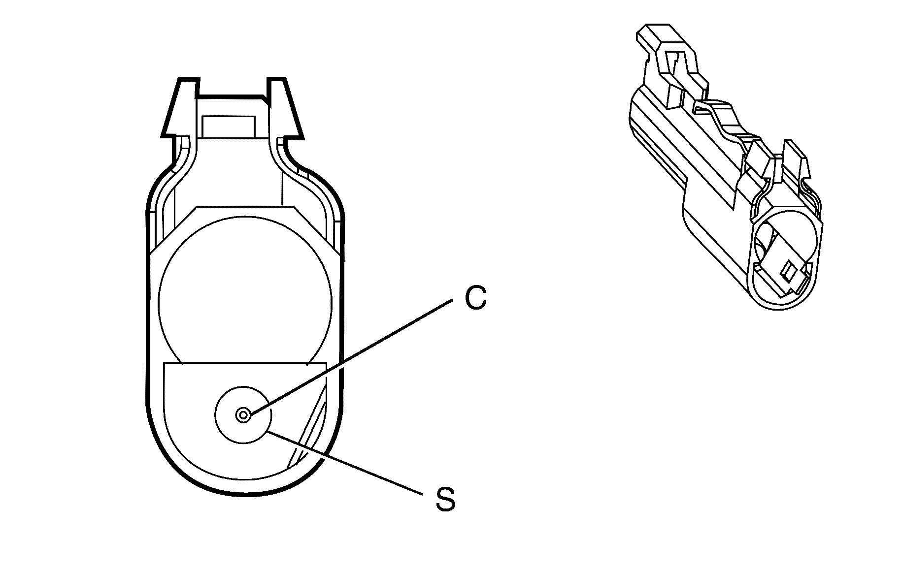
Connector Part Information | |||
Pin | Wire Colour | Wire Size | Function |
C | GY | 0.52 | Radio Antenna Post |
S | Bare | 0.35 | Radio Antenna Shield |
| |||
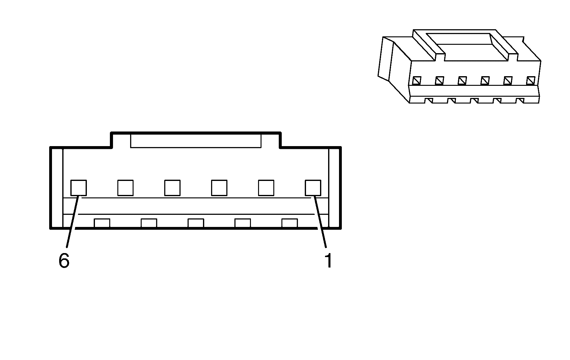
|---|---|---|---|
Connector Part Information | |||
Pin | Wire Colour | Wire Size | Function |
X1-1 | -- | -- | -- |
X1-2 | OG | 0.18 | XX |
X1-3 | TN | 0.18 | Ground |
X1-4 | YE/BK | 0.18 | XX |
X1-5 | L-GN/BK | 0.18 | XX |
X1-6 | -- | -- | -- |

| |||
|---|---|---|---|
Connector Part Information | |||
Pin | Wire Colour | Wire Size | Function |
X2-8 | -- | -- | -- |
X2-9 | WH | 0.18 | Auxiliary Audio Left Signal (+) |
X2-10 | PK | 0.18 | Auxiliary Audio Left Signal (-) |
X2-11 | RD | 0.18 | Auxiliary Audio Right Signal (+) |
X2-12 | GN | 0.18 | Auxiliary Audio Right Signal (-) |
X2-13 | BARE | 0.18 | Auxiliary Video Signal (-) |
X2-14 | BK | 0.18 | Auxiliary Video Signal (+) |
| |||
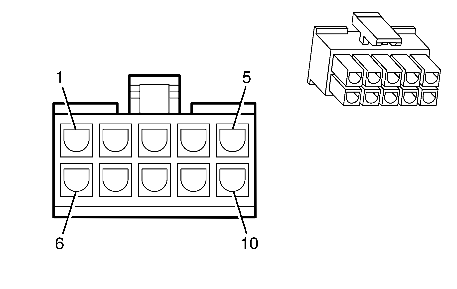
|---|---|---|---|
Connector Part Information | |||
Pin | Wire Colour | Wire Size | Function |
X1-1 | -- | -- | -- |
X1-2 | D-GN | 0.3 | Low Speed GMLAN Serial Data |
X1-3 | OG/YE | 0.5 | Battery Positive Voltage |
X1-4 | OG/YE | 0.5 | Battery Positive Voltage |
X1-5 | -- | -- | -- |
X1-6 | -- | -- | -- |
X1-7 | -- | -- | -- |
X1-8 | BK | 0.5 | Ground |
X1-9 | BK | 0.5 | Ground |
X1-10 | -- | -- | -- |
| |||
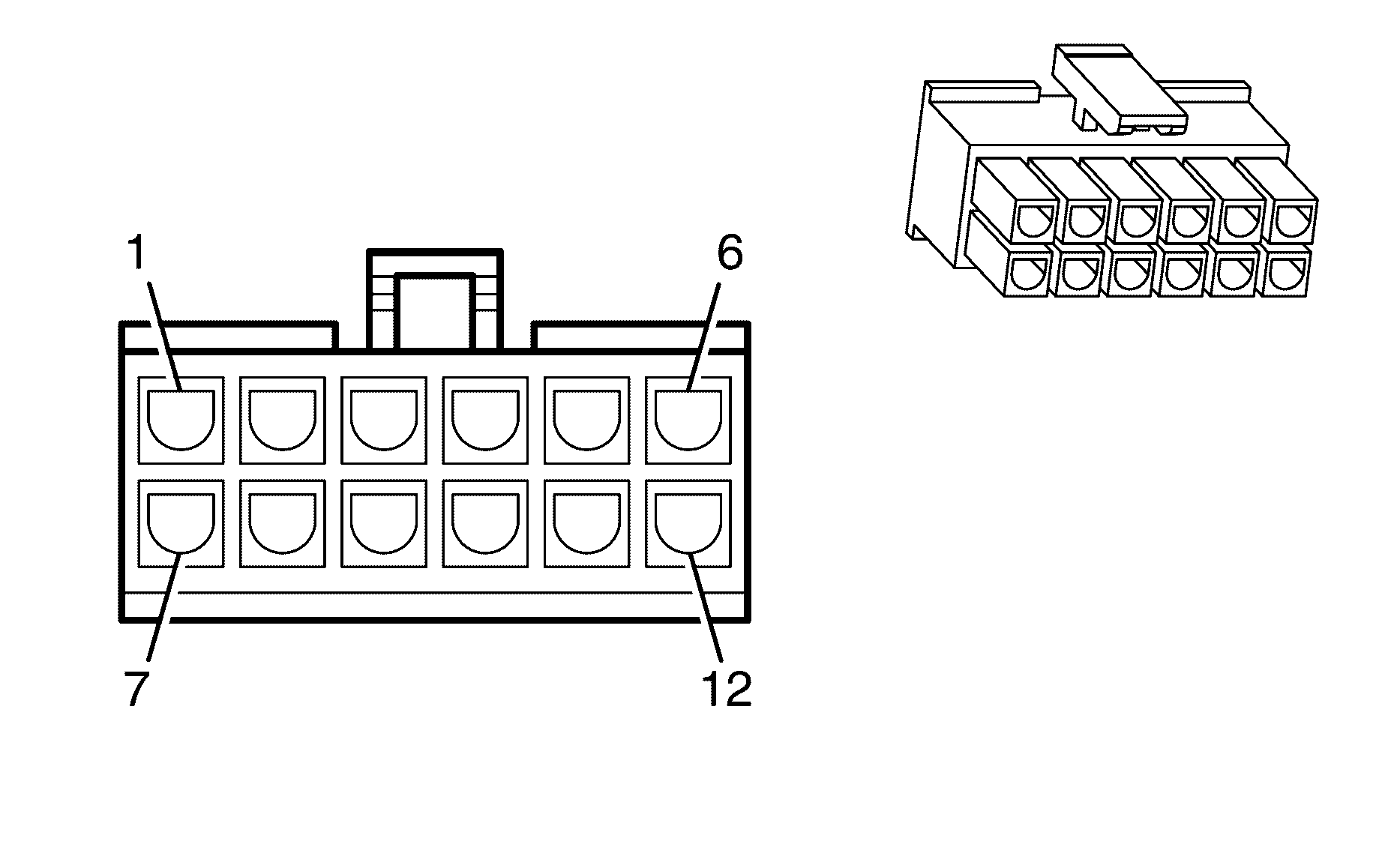
|---|---|---|---|
Connector Part Information | |||
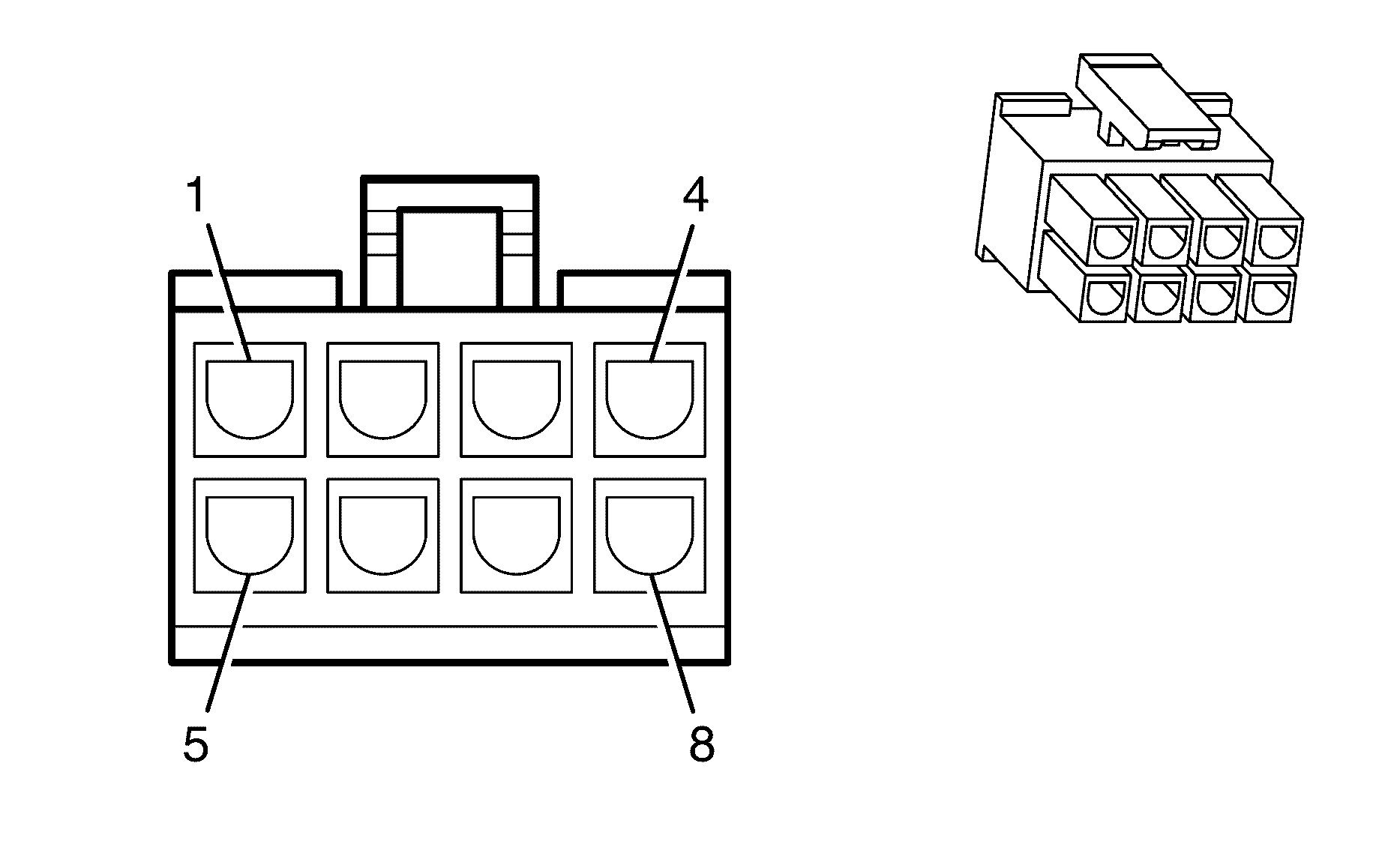
Pin | Wire Colour | Wire Size | Function |
X2-1 | -- | -- | -- |
X2-2 | -- | -- | -- |
X2-3 | -- | -- | -- |
X2-4 | -- | -- | -- |
X2-5 | -- | -- | -- |
X2-6 | -- | -- | -- |
X2-7 | -- | -- | -- |
X2-8 | -- | -- | -- |
X2-9 | -- | -- | -- |
X2-10 | -- | -- | -- |
X2-11 | -- | -- | -- |
X2-12 | -- | -- | -- |
| |||
|---|---|---|---|
Connector Part Information | |||
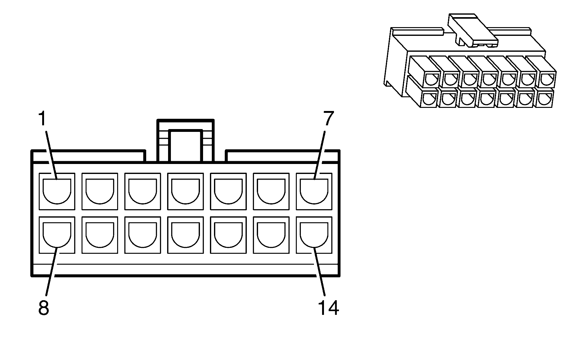
Pin | Wire Colour | Wire Size | Function |
X3-1 | BARE | 0.18 | Auxiliary Video Signal (-) |
X3-2 | RD | 0.18 | Auxiliary Audio Right Signal (+) |
X3-3 | WH | 0.18 | Auxiliary Audio Left Signal (+) |
X3-4 | -- | -- | -- |
X3-5 | BK | 0.18 | Auxiliary Video Signal (+) |
X3-6 | GN | 0.18 | Auxiliary Audio Right Signal (-) |
X3-7 | PK | 0.18 | Auxiliary Audio Left Signal (-) |
X3-8 | -- | -- | -- |
| |||
|---|---|---|---|
Connector Part Information | |||
Pin | Wire Colour | Wire Size | Function |
X4-1 | GY | 0.3 | DVD Video Signal (-) |
X4-2 | WH | 0.3 | DVD Audio Right Signal (+) |
X4-3 | L-BU | 0.3 | DVD Audio Left Signal (+) |
X4-4 | -- | -- | -- |
X4-5 | YE/BK | 0.32 | XX |
X4-6 | XXX | XXX | XX |
X4-7 | XXX | XXX | XX |
X4-8 | D-GN | 0.32 | DVD Video Signal (+) |
X4-9 | D-GN | 0.3 | DVD Audio Right Signal (-) |
X4-10 | WH/BK | 0.32 | DVD Audio Left Signal (-) |
X4-11 | -- | -- | -- |
X4-12 | GY | 0.32 | Passenger Door Lock Switch Low Reference |
X4-13 | XXX | XXX | XX |
X4-14 | XXX | XXX | XX |

| |||
|---|---|---|---|
Connector Part Information | |||
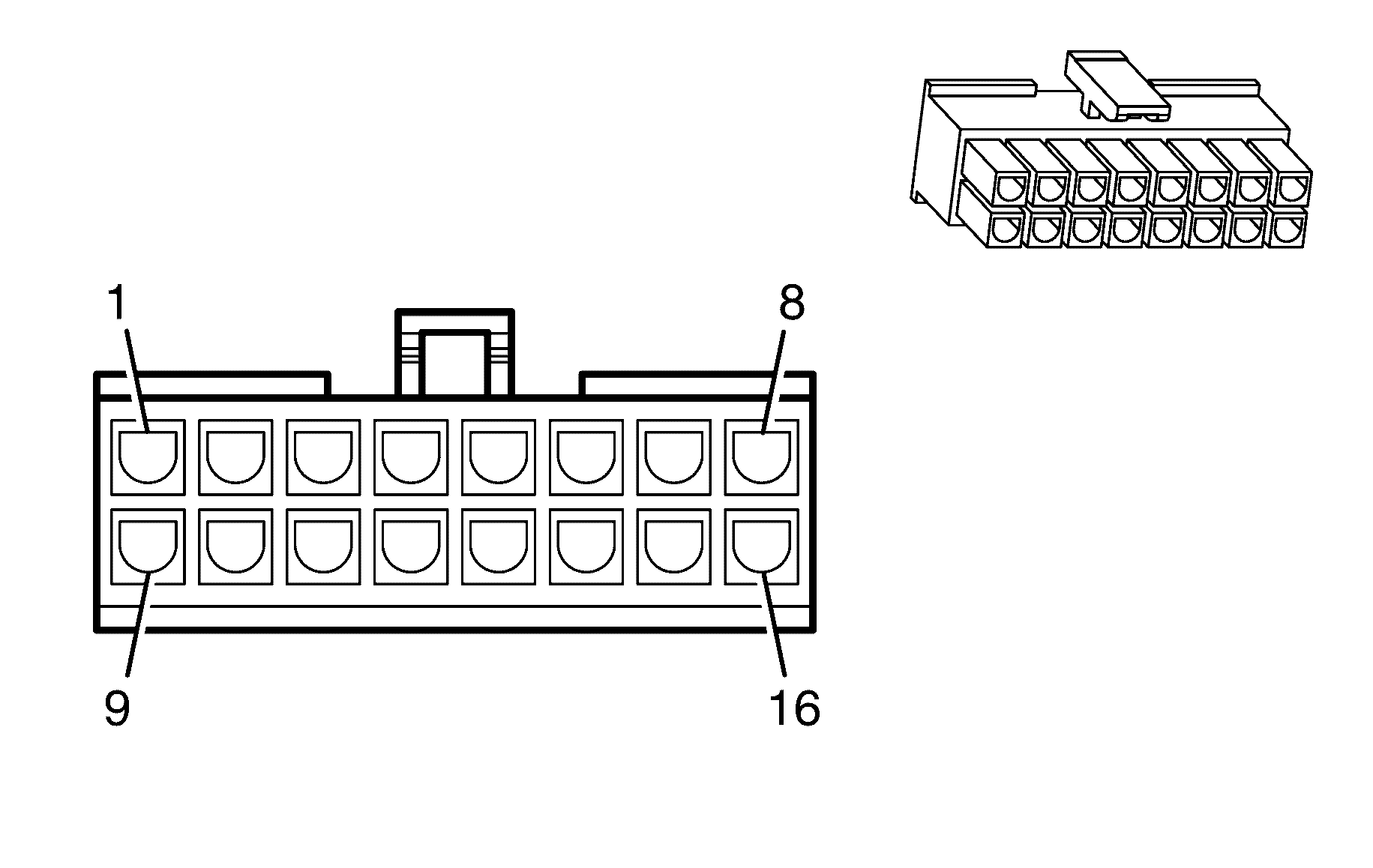
Pin | Wire Colour | Wire Size | Function |
X5-1 | BK | 0.0 | DVD Video Signal (-) |
X5-2 | RD | 0.18 | DVD Audio Right Signal (+) |
X5-3 | WH | 0.18 | DVD Audio Left Signal (+) |
X5-4 | BARE | 0.18 | Drain Wire |
X5-5 | GY | 0.18 | XX |
X5-6 | PU | 0.18 | Ground |
X5-7 | YE | 0.18 | XX |
X5-8 | BK | 0.18 | DVD Video Signal (+) |
X5-9 | RD | 0.18 | DVD Audio Right Signal (-) |
X5-10 | WH | 0.18 | DVD Audio Left Signal (-) |
X5-11 | -- | -- | -- |
X5-12 | BU | 0.18 | XX |
X5-13 | -- | -- | -- |
X5-14 | -- | -- | -- |
| |||
|---|---|---|---|
Connector Part Information | |||
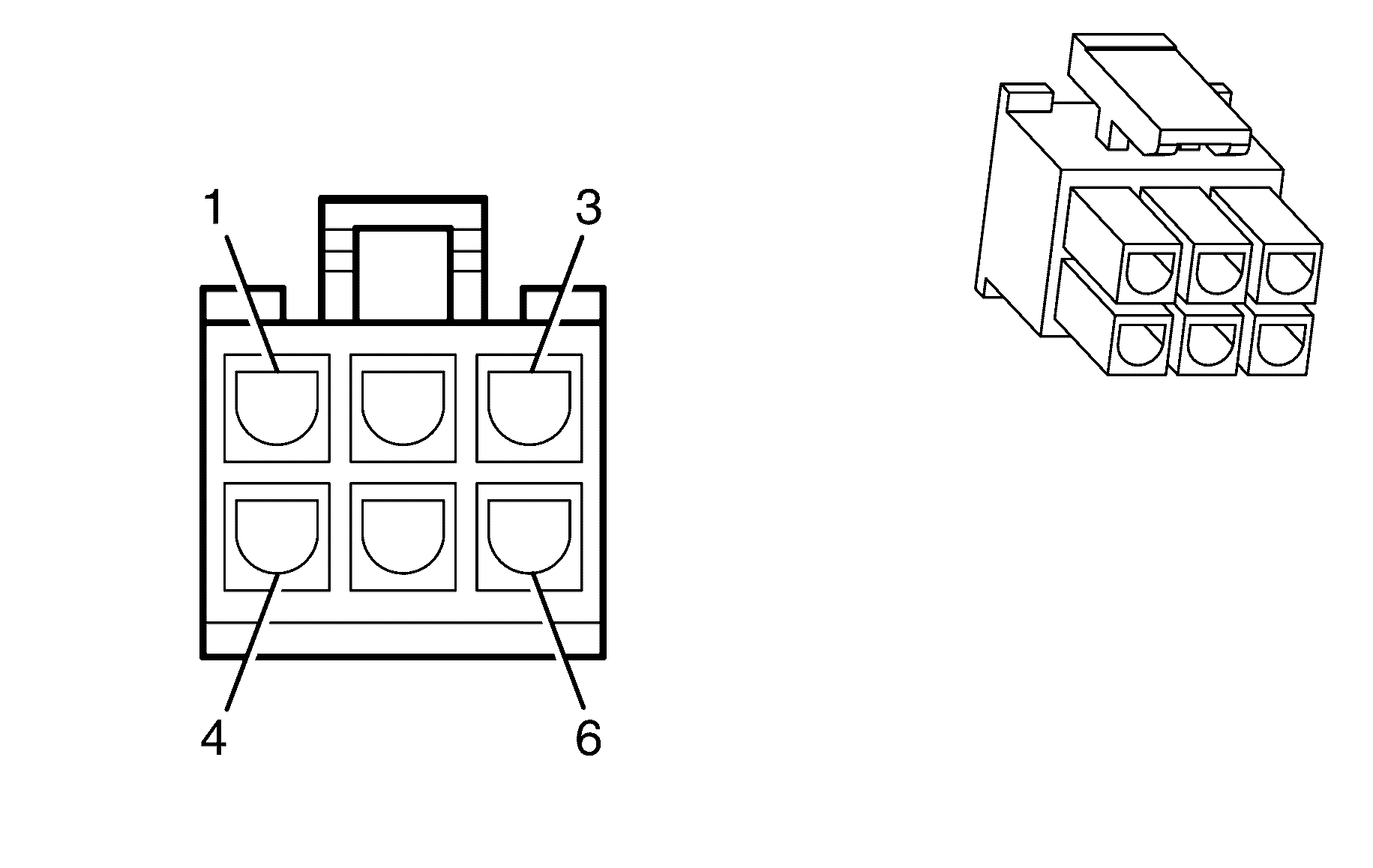
Pin | Wire Colour | Wire Size | Function |
X6-1 | -- | -- | -- |
X6-2 | -- | -- | -- |
X6-3 | -- | -- | -- |
X6-4 | -- | -- | -- |
X6-5 | -- | -- | -- |
X6-6 | -- | -- | -- |
X6-7 | -- | -- | -- |
X6-8 | -- | -- | -- |
X6-9 | -- | -- | -- |
X6-10 | -- | -- | -- |
X6-11 | -- | -- | -- |
X6-12 | -- | -- | -- |
X6-13 | -- | -- | -- |
X6-14 | -- | -- | -- |
X6-15 | -- | -- | -- |
X6-16 | -- | -- | -- |
| |||
|---|---|---|---|
Connector Part Information | |||
Pin | Wire Colour | Wire Size | Function |
X7-1 | BU | 0.18 | XX |
X7-2 | L-BU | 0.18 | Ground |
X7-3 | -- | -- | -- |
X7-4 | XX | XX | XX |
X7-5 | GY | 0.18 | XX |
X7-6 | RD | 0.18 | XX |

| |||
|---|---|---|---|
Connector Part Information | |||
Pin | Wire Colour | Wire Size | Function |
X8-1 | BK | 0.5 | DVD Video Signal (-) |
X8-2 | -- | -- | -- |
X8-3 | RD | 0.5 | Right Audio Signal (+) |
X8-4 | WH | 0.5 | Left Audio Signal (+) |
X8-5 | -- | -- | -- |
X8-6 | BK | 0.5 | DVD Video Signal (+) |
X8-7 | -- | -- | -- |
X8-8 | WH/RD | 0.5 | Common Audio Signal (-) |
| |||
|---|---|---|---|
Connector Part Information | |||
Pin | Wire Colour | Wire Size | Function |
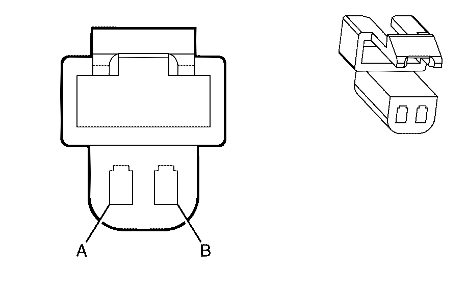
A | GY | 0.5 | Left Front Speaker Output (-) |
B | TN | 0.5 | Left Front Speaker Output (+) |

| |||
|---|---|---|---|
Connector Part Information | |||
Pin | Wire Colour | Wire Size | Function |
A | L-BU | 0.5 | Front Center Speaker Output (-) |
B | OG | 0.5 | Front Center Speaker Output (+) |

| |||
|---|---|---|---|
Connector Part Information | |||
Pin | Wire Colour | Wire Size | Function |
A | D-GN | 0.5 | Right Front Speaker Output (-) |
B | L-GN | 0.5 | Right Front Speaker Output (+) |

| |||
|---|---|---|---|
Connector Part Information | |||
Pin | Wire Colour | Wire Size | Function |
A | GY | 0.5 | Left Front Speaker Output (-) |
B | TN | 0.5 | Left Front Speaker Output (+) |
| |||
|---|---|---|---|
Connector Part Information | |||
Pin | Wire Colour | Wire Size | Function |
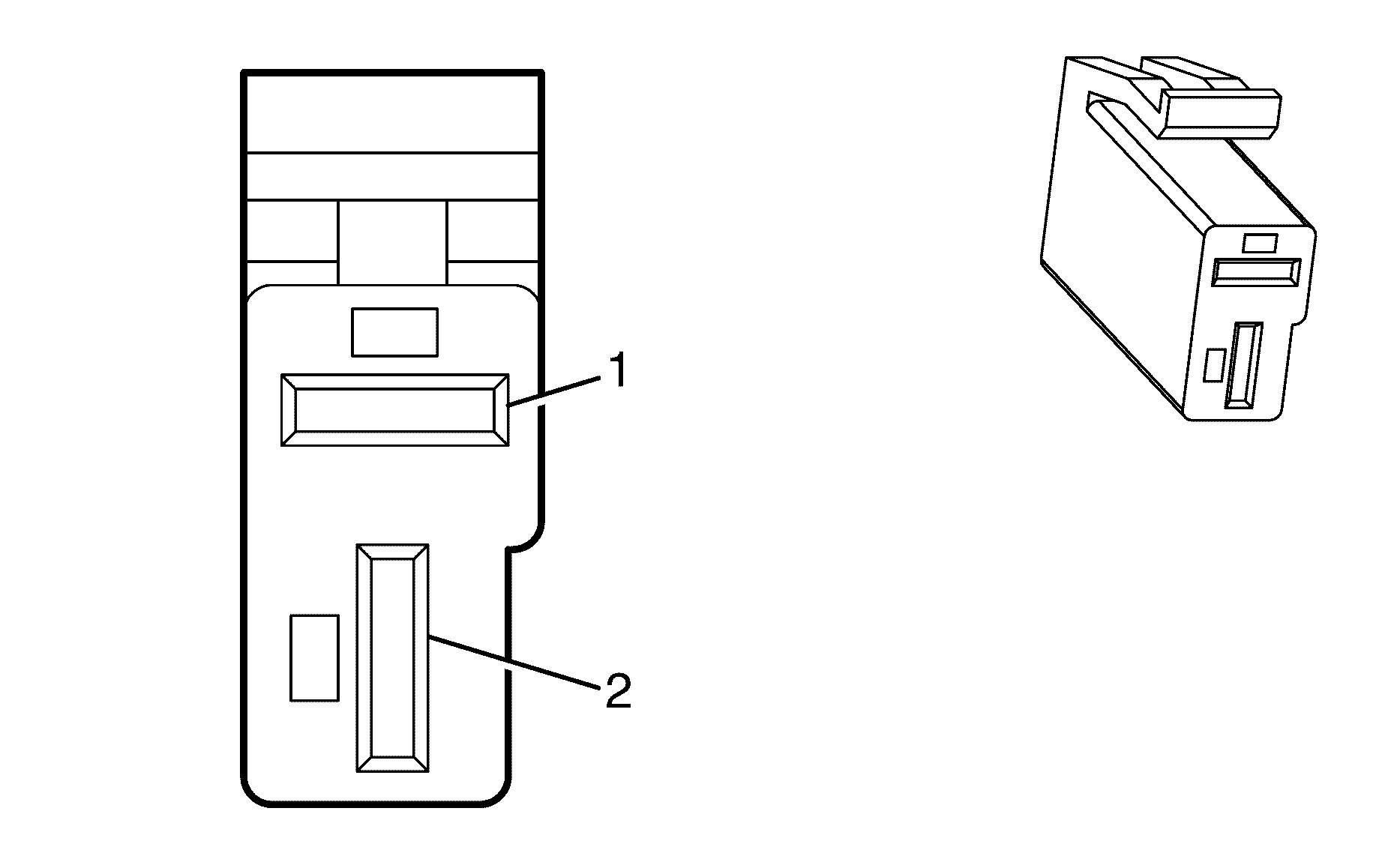
A | GY | 0.5 | Left Front Speaker Output (-) |
B | BN | 0.5 | Left Front Speaker Output (+) |
| |||
|---|---|---|---|
Connector Part Information | |||
Pin | Wire Colour | Wire Size | Function |
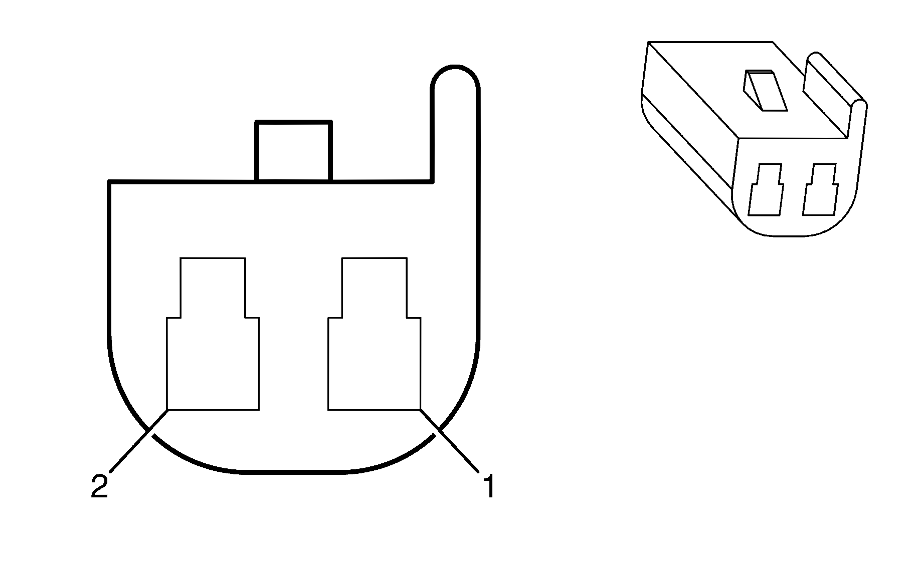
1 | TN | 0.3 | Left Front Speaker Output (+) |
2 | GY | 0.3 | Left Front Speaker Output (-) |

| |||
|---|---|---|---|
Connector Part Information | |||
Pin | Wire Colour | Wire Size | Function |
A | YE | 0.5 | Left Rear Speaker Output (-) |
B | BN | 0.5 | Left Rear Speaker Output (+) |
| |||
|---|---|---|---|
Connector Part Information | |||
Pin | Wire Colour | Wire Size | Function |
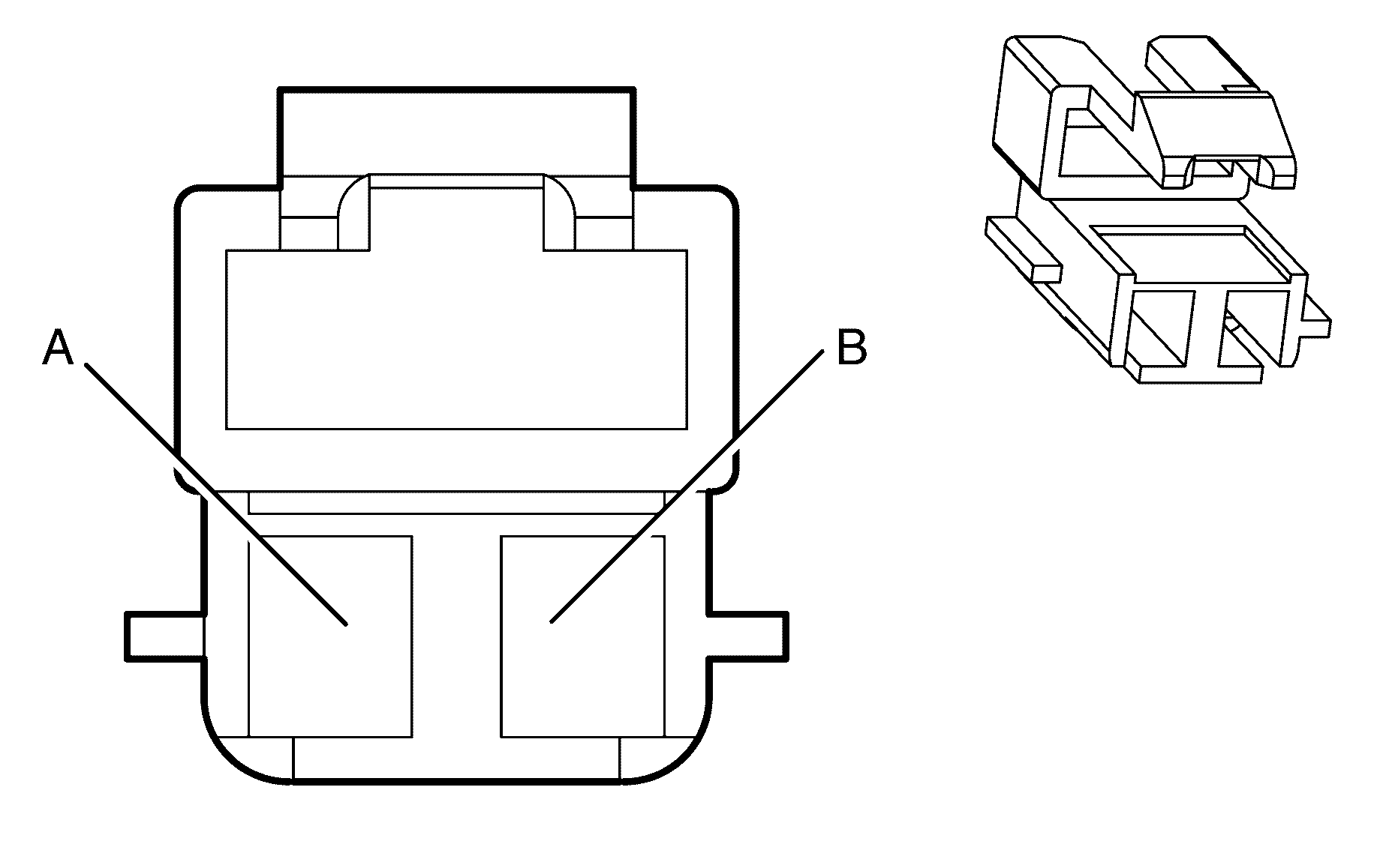
1 | D-BU/WH | 1.0 | Left Rear Subwoofer Speaker Output (+) |
2 | L-GN/BK | 1.0 | Left Rear Subwoofer Speaker Output (-) |

| |||
|---|---|---|---|
Connector Part Information | |||
Pin | Wire Colour | Wire Size | Function |
A | D-GN | 0.75 | Right Front Speaker Output (-) |
B | L-GN/BK | 0.75 | Right Front Speaker Output (+) |

| |||
|---|---|---|---|
Connector Part Information | |||
Pin | Wire Colour | Wire Size | Function |
1 | L-GN | 0.3 | Right Front Speaker Output (+) |
2 | D-GN | 0.3 | Right Front Speaker Output (-) |

| |||
|---|---|---|---|
Connector Part Information | |||
Pin | Wire Colour | Wire Size | Function |
A | L-BU | 0.5 | Right Rear Speaker Output (-) |
B | D-BU | 0.5 | Right Rear Speaker Output (+) |

| |||
|---|---|---|---|
Connector Part Information | |||
Pin | Wire Colour | Wire Size | Function |
1 | D-GN | 1.0 | Right Rear Subwoofer Speaker Output (+) |
2 | L-BU/BK | 1.0 | Right Rear Subwoofer Speaker Output (-) |

| |||
|---|---|---|---|
Connector Part Information | |||
Pin | Wire Colour | Wire Size | Function |
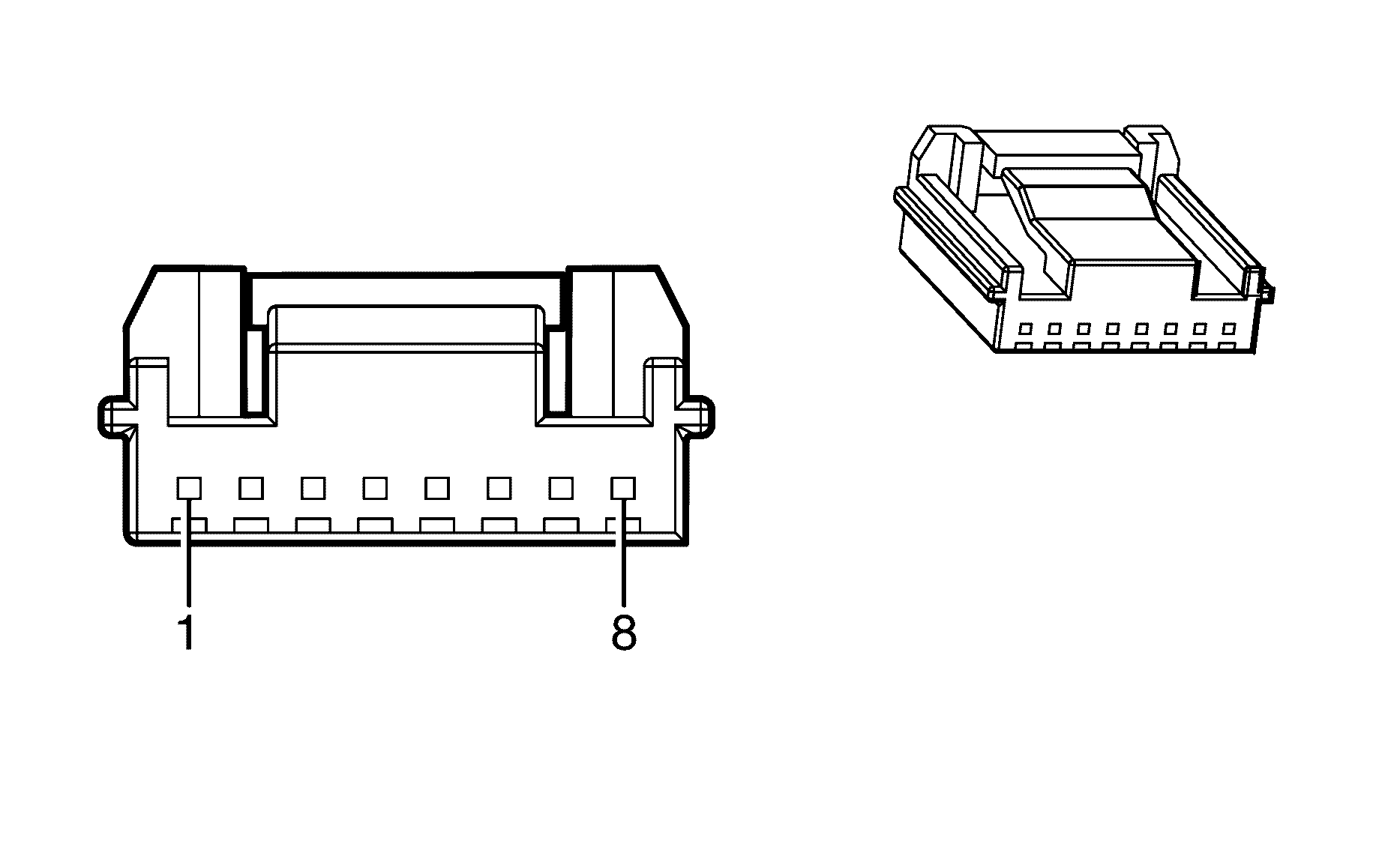
1 | GY/BU | 0.3 | Steering Wheel Resistor Ladder Right Signal #2 |
2 | YE | 0.3 | Steering Wheel Resistor Ladder Right Signal #1 |
3 | BN | 0.3 | Steering Wheel Resistor Ladder Left Signal #1 |
4 | L-BU | 0.3 | Steering Wheel Resistor Ladder Left Signal #2 |
5 | GN | 0.3 | Steering Wheel Controls Low Reference |
6 | OG/BK | 0.3 | Steering Wheel Controls Signal |
7 | BK | 0.3 | Ground |
8 | PU | 0.3 | I/P Dimming Control |
| |||
|---|---|---|---|
Connector Part Information | |||
Pin | Wire Colour | Wire Size | Function |
1 | YE | 0.18 | XX |
2 | -- | -- | -- |
3 | PU | 0.18 | Ground |
4 | -- | -- | -- |
5 | GY | 0.18 | XX |
6 | BU | 0.18 | XX |
7 | BARE | 0.18 | Drain Wire |
8 | -- | -- | -- |
9 | WH | 0.18 | DVD Audio Left Signal (+) |
10 | WH | 0.18 | DVD Audio Left Signal (-) |
11 | RD | 0.18 | DVD Audio Right Signal (+) |
12 | RD | 0.18 | DVD Audio Right Signal (-) |
13 | BK | 0.18 | DVD Video Signal (-) |
14 | BK | 0.18 | DVD Video Signal (+) |
Entertainment/Communication Connector End Views Bluetooth
| Table 1: | Bluetooth Connector |
| Table 2: | Bluetooth Microphone |
| Table 3: | Bluetooth Module |
| Table 4: | Steering Wheel Controls Switch Assembly |
| |||
|---|---|---|---|
Connector Part Information | |||
Pin | Wire Colour | Wire Size | Function |
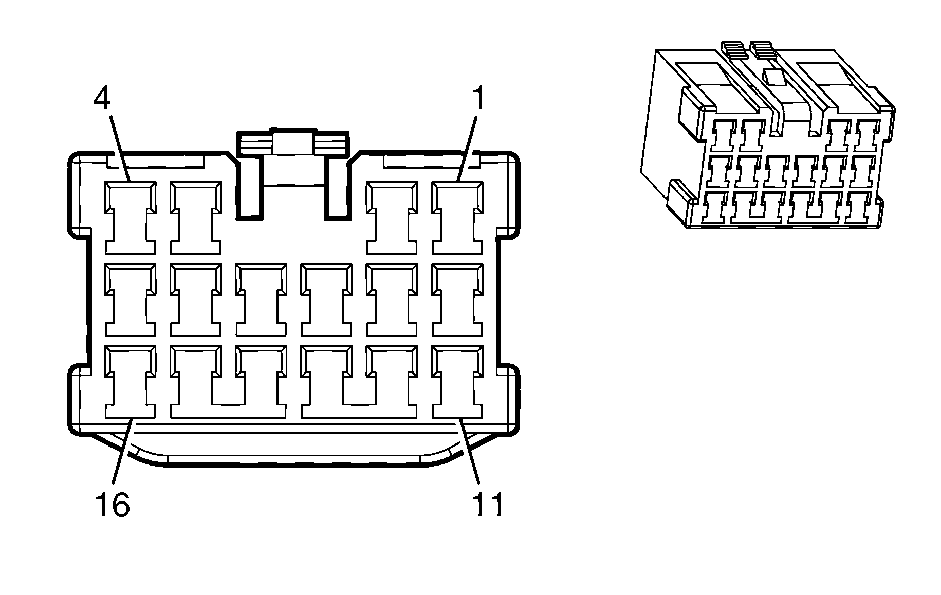
X1-1 | OG/WH | 0.5 | Battery Positive Voltage |
X1-2 | PK/BU | 0.5 | Ignition 1 Voltage |
X1-3 | L-GN | 0.5 | Backup Lamp Supply Voltage |
X1-4 | D-GN | 0.3 | Low Speed GMLAN Serial Data |
X1-5 | BN | 0.3 | Accessory Voltage |
X1-6 | BU | 0.3 | Bluetooth Connector |
X1-7 | OG/BK | 0.3 | Remote Playback Device Left Audio Signal |
X1-8 | L-BU | 0.3 | Remote Playback Device Audio Common Signal |
X1-9 | WH | 0.3 | Mute Signal |
X1-10 | BK | 0.3 | Ground |
X1-11 | D-BU | 0.3 | Cellular Telephone Voice Signal |
X1-12 | L-BU/BK | 0.3 | Cellular Telephone Voice Low Reference |
X1-13 | YE/BK | 0.3 | Cellular Telephone Mute Signal |
X1-14 | GY | 0.5 | Left Front Speaker Output (-) |
L-BU | 0.85 | Front Center Speaker Output (-) | |
X1-15 | TN | 0.5 | Left Front Speaker Output (+) |
YE | 0.85 | Front Center Speaker Output (+) | |
X1-16 | -- | -- | Not Used |
| |||
|---|---|---|---|
Connector Part Information | |||
Pin | Wire Colour | Wire Size | Function |
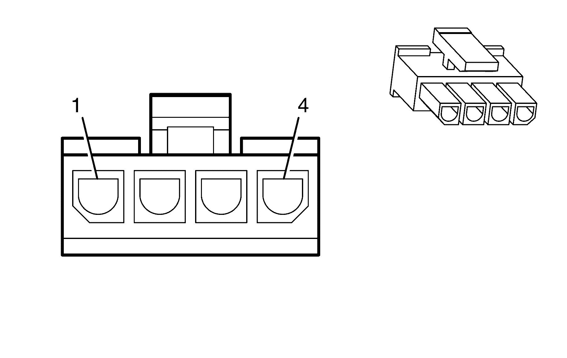
1 | BU | 0.3 | Microphone Signal |
2 | -- | -- | Not Used |
3 | -- | -- | Not Used |
4 | PK/BK | 0.3 | Microphone Return |
| |||
|---|---|---|---|
Connector Part Information | |||
Pin | Wire Colour | Wire Size | Function |
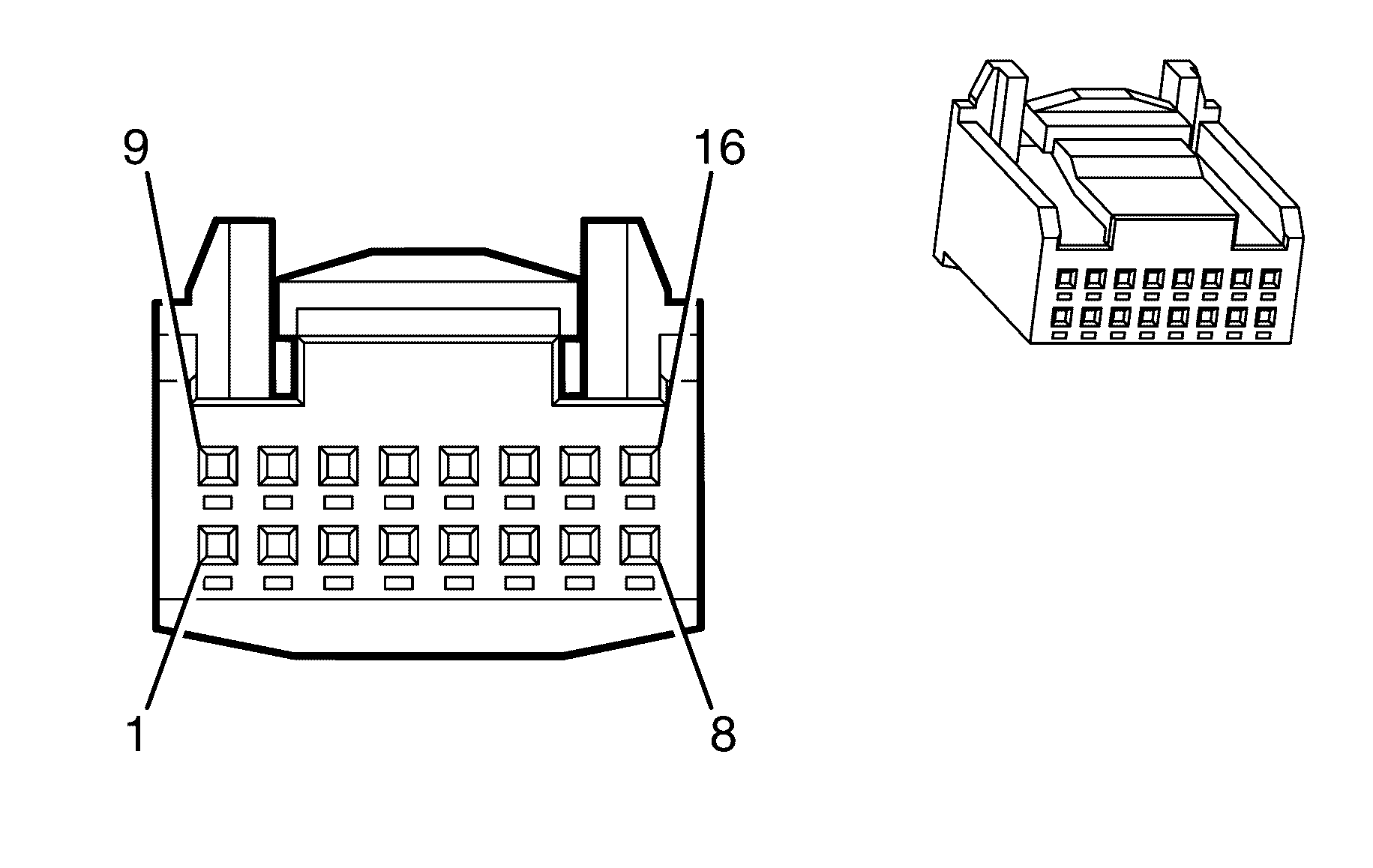
1 | L-BU/BK | 0.3 | Cellular Telephone Voice Low Reference |
2 | -- | -- | Not Used |
3 | -- | -- | Not Used |
4 | BU | 0.3 | Not Used |
5 | BU | 0.3 | Microphone Signal |
6 | YE/BK | 0.3 | Cellular Telephone Mute Signal |
7 | YE | 0.3 | Accessory Voltage |
8 | -- | -- | Not Used |
9 | D-BU | 0.3 | Cellular Telephone Voice Signal |
10 | -- | -- | Not Used |
11 | -- | -- | Not Used |
12 | PK/BK | 0.3 | Microphone Return |
13 | -- | -- | Not Used |
14 | -- | -- | Not Used |
15 | BK | 0.5 | Ground |
16 | OG/WH | 0.5 | Battery Positive Voltage |

| |||
|---|---|---|---|
Connector Part Information | |||
Pin | Wire Colour | Wire Size | Function |
1 | GY/BU | 0.3 | Steering Wheel Resistor Ladder Right Signal #2 |
2 | YE | 0.3 | Steering Wheel Resistor Ladder Right Signal #1 |
3 | BN | 0.3 | Steering Wheel Resistor Ladder Left Signal #1 |
4 | L-BU | 0.3 | Steering Wheel Resistor Ladder Left Signal #2 |
5 | GN | 0.3 | Steering Wheel Controls Low Reference |
6 | OG/BK | 0.3 | Steering Wheel Controls Signal |
7 | BK | 0.3 | Ground |
8 | PU | 0.3 | I/P Dimming Control |
