Notice: Refer to Test Probe Notice in the Preface section.

- Disconnect the electrical harness connector for the
circuit being tested, if necessary.
- Enable the circuit and/or system being tested. Use the following methods:
| • | Turn the ignition to the ON position, with the engine OFF. |
| • | Turn the engine to the ON position. |
| • | Turn the circuit and/or system to the ON position with a scan tool in
Output Controls. |
| • | Turn the switch for the circuit and/or system being tested to the ON position. |
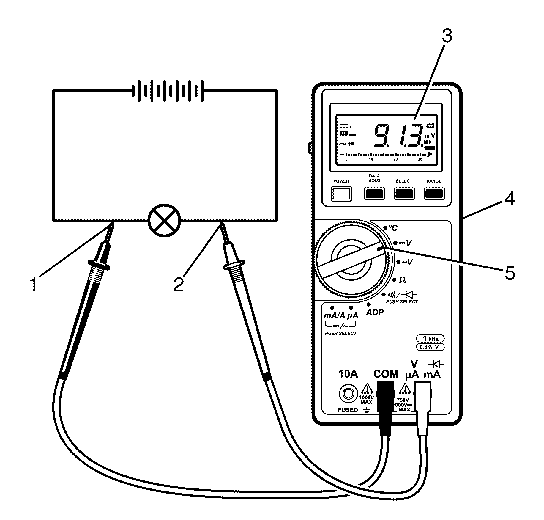
- Select the V (AC) or V (DC) position (5) on the Digital Multimeter (4)
depending on the circuit to be tested.
- Connect the positive lead (2) of the Digital Multimeter (4)
to the point of the circuit to be tested.
- Connect the negative lead (1) of the Digital Multimeter to a known
good ground.
- The Digital Multimeter (4) displays the voltage measured at that
point (3).

