Defroster Valve Actuator Replacement LHD
Removal Procedure
- Remove the glove box assembly. Refer to Instrument Panel Compartment Replacement .
- Remove Left side floor duct. Refer to Floor Air Outlet Duct Replacement - Left Side .
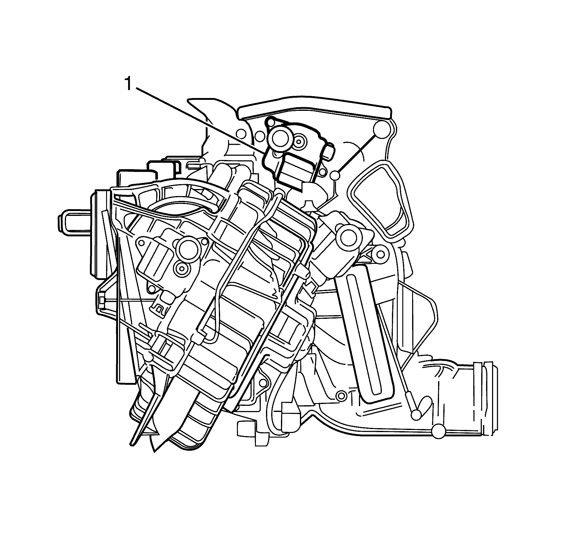
- Locate the defrost mode actuator (1) on the HVAC module assembly, passenger side.
- Disconnect the electrical connector from the defrost mode actuator.
- Remove the defrost mode actuator to HVAC module assembly retaining screws.
- Remove the defrost mode actuator from the HVAC module assembly.
- Remove the rear passenger mode rod clip (1) from the mode door lever to assist actuator replacement.
- Remove the rear passenger mode lever as one piece from the HVAC module assembly, manoeuvring the rod through the actuator mountings.
- Detach the rear passenger mode rod from the defrost mode actuator.
- Gently remove the rear passenger mode lever from the defrost mode actuator.
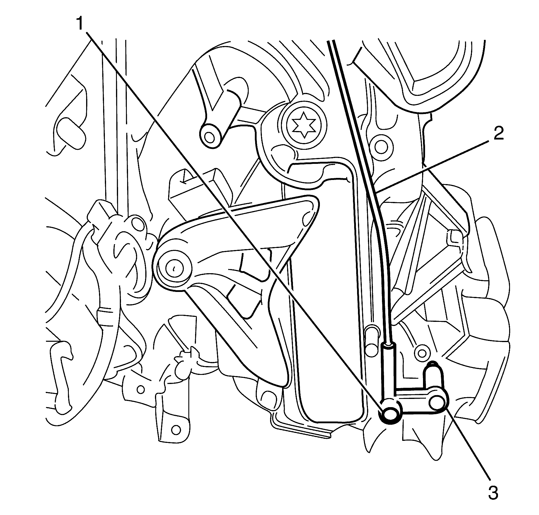
Important: Squeeze the clip locators together with suitable tool.
Important: Rotate the rear passenger mode rod to match the actuator lever locking position opening, then remove rear passenger mode rod.
Important: Take note of the rear passenger mode lever position in relation to the actuator housing.
Installation Procedure
- Install the rear passenger mode lever to the defrost mode actuator.
- Attach the rear passenger mode rod to the actuator.
- Install the rear passenger mode lever as one piece, manoeuvring the rod through the actuator mountings.
- Install the rear passenger mode rod (1) clip to the mode door lever.
- Install the defrost mode actuator (1) to the HVAC.
- Install the defrost mode actuator to HVAC module assembly retaining screws.
- Connect the electrical connector (1) to the defrost mode actuator.
- Install Left side floor duct. Refer to Floor Air Outlet Duct Replacement - Left Side .
- Install the glove box assembly. Refer to Instrument Panel Compartment Replacement .
- Perform HVAC system relearn.


Notice: Refer to Fastener Notice in the Preface section.
Tighten
Tighten the bolts to 1.5 N·m (13 lb in).
Defroster Valve Actuator Replacement RHD
Removal Procedure
- Remove the I/P lower trim plate assembly. Refer to Instrument Panel Insulator Panel Replacement - Left Side .
- Remove the instrument panel outer trim cover. Refer to Instrument Panel Outer Trim Cover Replacement .
- Remove the I/P compartment assembly. Refer to Instrument Panel Compartment Replacement .
- Remove the left side floor duct. Refer to Floor Air Outlet Duct Replacement - Left Side .
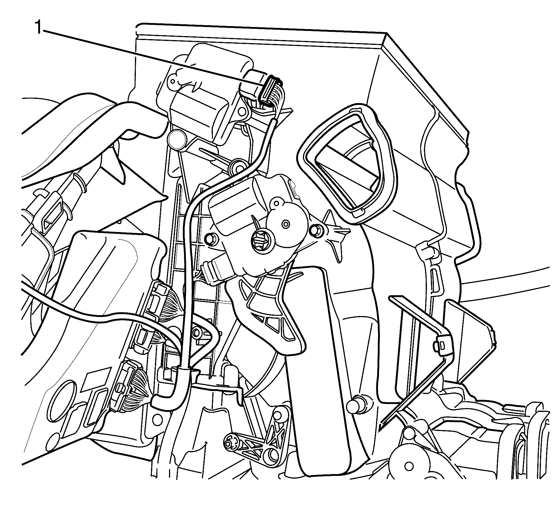
- Disconnect the defrost mode actuator electrical connector (1).
- Detach the rear passenger mode rod (2) from the mode door lever (3).
- Remove the defrost mode actuator to HVAC module assembly retaining screws (2).
- Remove the defrost mode actuator and the rear passenger mode lever (1) from the HVAC module assembly (3).
- Detach the rear passenger mode rod (1) from the defrost mode actuator (4).
- Gently remove the rear passenger mode lever (3) from the defrost mode actuator (4).


Important: Using a suitable tool, squeeze the rear passenger mode rod to rear passenger mode door lever retaining clip (1) to detach the rear passenger mode rod (2) from the rear passenger mode door lever (3).
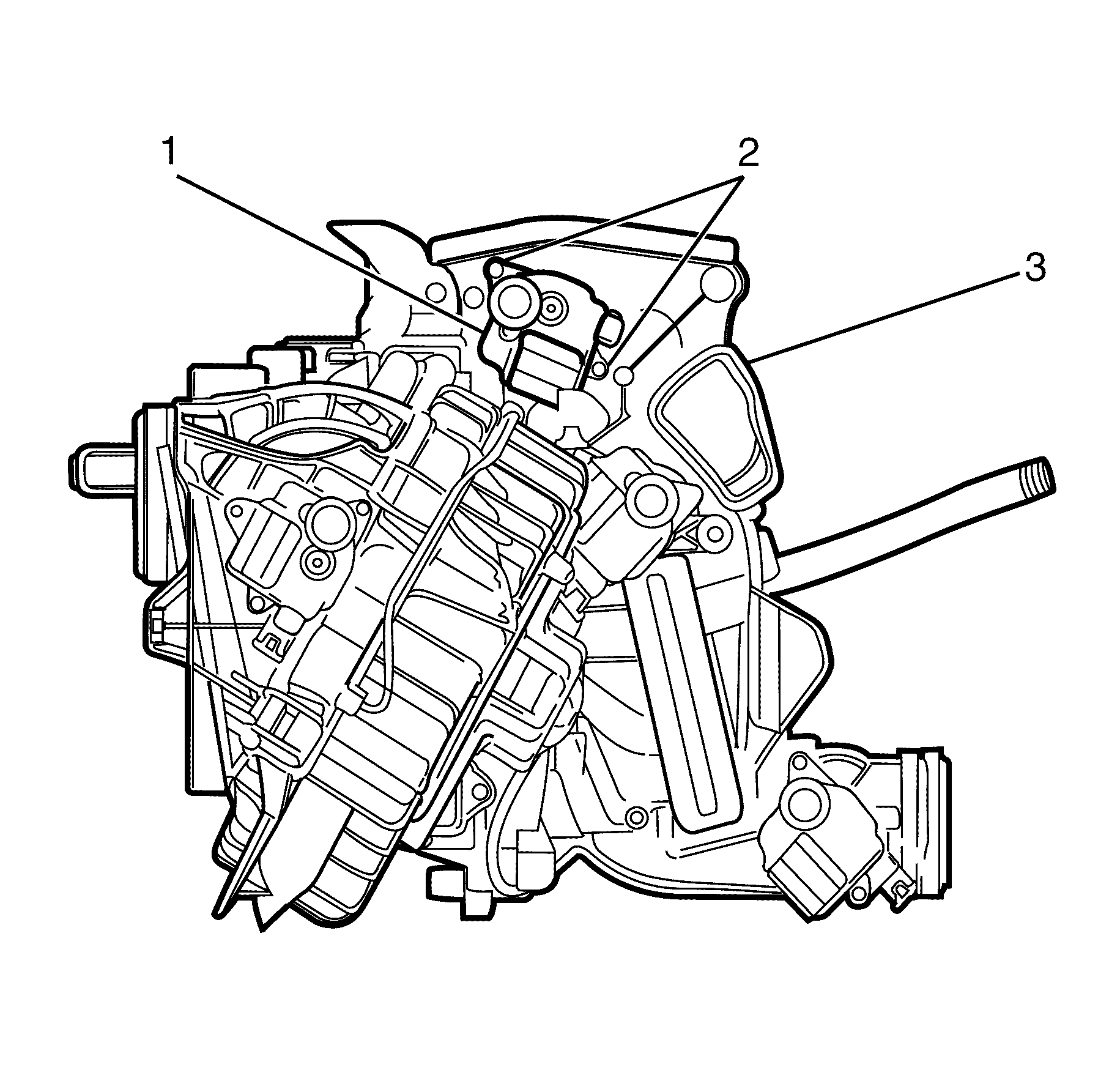
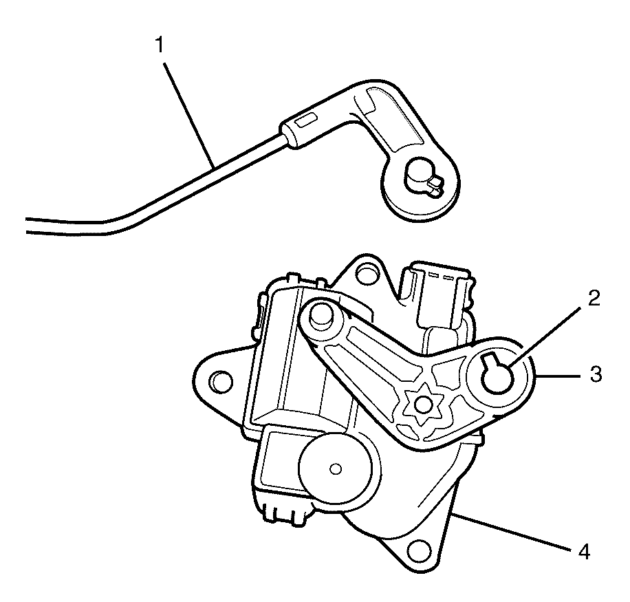
Important: Rotate the rear passenger mode rod (1) to match the actuator lever locking position opening (2), then remove rear passenger mode rod (1).
Important: Take note of the rear passenger mode lever (3) position in relation to the defrost mode actuator (4).
Installation Procedure
- Install the rear passenger mode lever (3) to the defrost mode actuator (4).
- Attach the rear passenger mode rod (1) to the actuator (4).
- Install the and the rear passenger mode lever (1) to the HVAC module assembly (3).
- Install the defrost mode actuator to HVAC module assembly retaining screws (2).
- Attach the rear passenger mode rod (2) to the mode door lever (3).
- Connect the defrost mode actuator electrical connector (1).
- Install left side floor duct. Refer to Floor Air Outlet Duct Replacement - Left Side .
- Install the I/P compartment assembly. Refer to Instrument Panel Compartment Replacement .
- Install instrument panel outer trim cover. Refer to Instrument Panel Outer Trim Cover Replacement .
- Install the I/P lower trim plate assembly. Refer to Instrument Panel Insulator Panel Replacement - Left Side .
- Perform HVAC system relearn. Refer to HVAC Control Module Programming and Setup .

Important: Rotate the rear passenger mode rod (1) to match the actuator lever locking position opening (2), to install the rear passenger mode rod (1).

Notice: Refer to Fastener Notice in the Preface section.
Tighten
Tighten the screws to 1 N·m (9 lb in).

Important: Make sure the rear passenger mode rod to rear passenger mode door lever retaining clip (1) is correctly engaged to prevent the rear passenger mode door lever (3) from functioning incorrectly.

