Rear End Panel Filler Replacement Sportwagon
Removal Procedure
- Disable the SIR system. Refer to SIR Disabling and Enabling.
- Disconnect the negative battery cable. Refer to Battery Negative Cable Disconnection and Connection.
- Remove the rear end trim finish panel. Refer to Rear End Trim Finish Panel Replacement.
- Remove the rear compartment floor panel carpet. Refer to Rear Compartment Floor Panel Carpet Replacement.
- Remove the load floor stationary panel carpet. Refer to Load Floor Stationary Panel Carpet Replacement.
- Remove the load floor front panel carpet. Refer to Load Floor Front Panel Carpet Replacement.
- Remove the liftgate weatherstrip. Refer to Liftgate Weatherstrip Replacement.
- Remove the quarter inner trim finish panel. Refer to Quarter Inner Trim Finish Panel Replacement.
- Remove the battery. Refer to Battery Replacement.
- Remove the battery tray. Refer to Battery Tray Replacement.
- Remove the liftgate. Refer to Liftgate Replacement.
- Remove the rear bumper fascia. Refer to Rear Bumper Fascia Replacement.
- Remove the tail lamp. Refer to Tail Lamp Assembly and /or Backup, Sidemarker, Stop, Turn Signal Bulb Replacement.
- Note the location and remove the sealers and anti-corrosion materials from the repair area, as necessary. Refer to Anti-Corrosion Treatment and Repair.
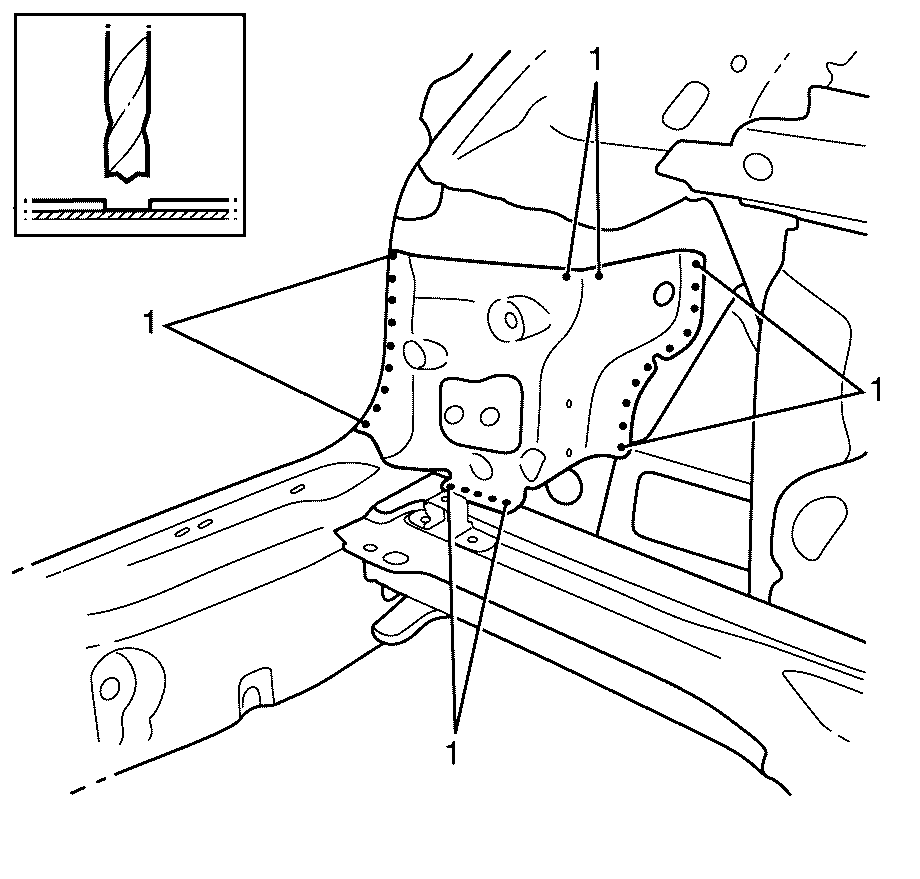
- Locate, mark and drill out the spot welds attaching the Tail Lamp Inner Filler Panel to body side assembly and floor assembly (1).
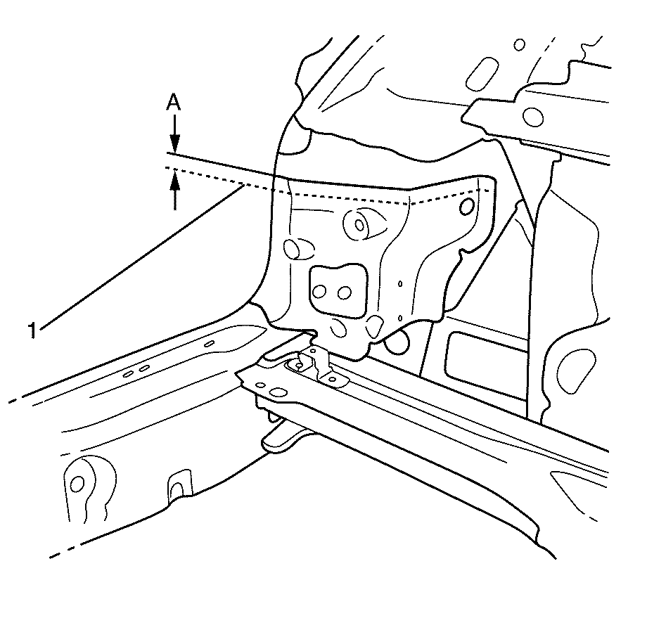
- Mark a horizontal cut line 25 mm (1.0 in) (Dimension A) below the top of the Tail Lamp Inner Filler Panel. The cut line must be parallel with the top of the Tail Lamp Inner Filler Panel.
- Cut along the cut line (1) on the Tail Lamp Inner Filler Panel with a suitable cutting tool.
- Remove the lower portion of the Tail Lamp Inner Filler Panel from the vehicle.
- Using a suitable tool remove the remaining strip of Tail Lamp Inner Filler Panel from the inner body side. Ensure all traces of old adhesive are removed.
Caution: Refer to Approved Equipment for Collision Repair Caution in the Preface section.
Caution: Refer to Safety Glasses Caution in the Preface section.
Caution: Refer to Foam Sound Deadeners Caution in the Preface section.
Caution: Refer to Battery Disconnect Caution in the Preface section.

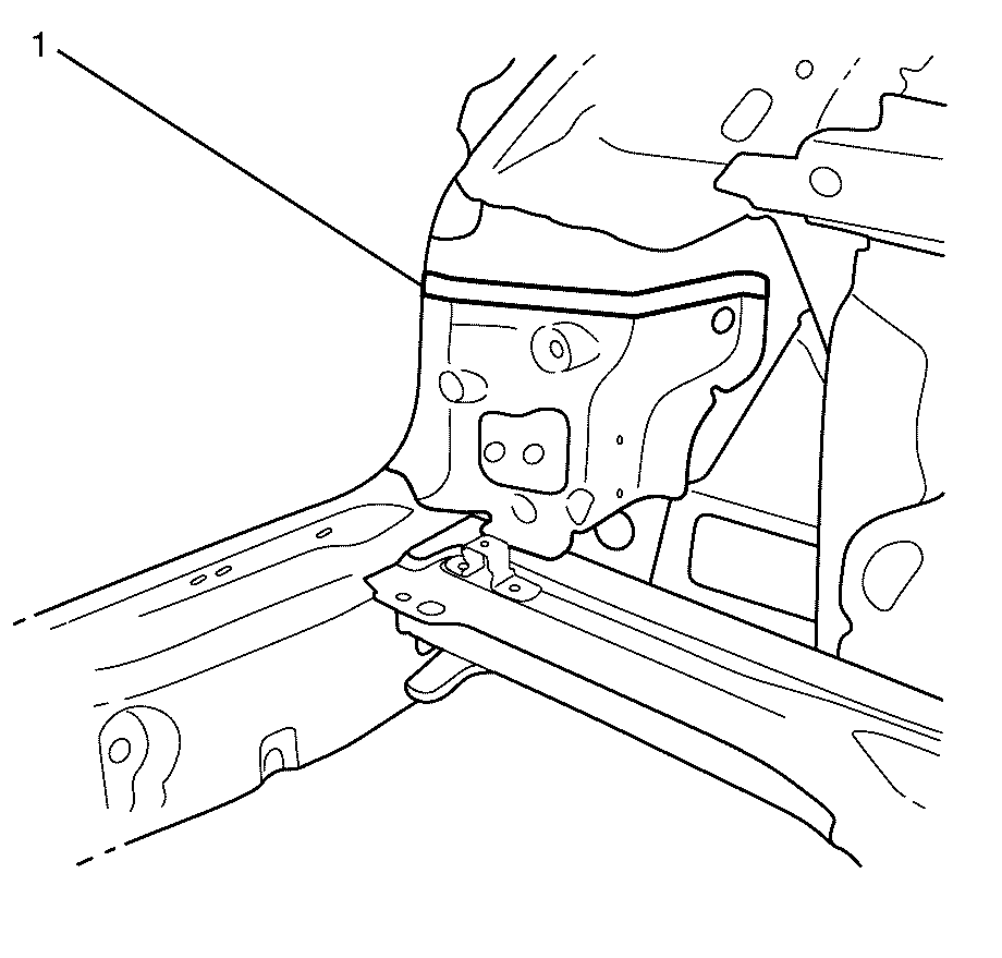
Important: Note the location of the factory adhesive and sealants for installation of the service assembly.
Important: Note the number and location of the factory welds for the installation of the service assembly.

Important: The Tail Lamp Inner Filler Panel is attached to the vehicle with spotwelds and a bead of adhesive along the top.
Important: Only cut through the Tail Lamp Inner Filler Panel. Do not damage any inner panels or reinforcements.
Important: Do not damage any inner panels or reinforcements.
Installation Procedure
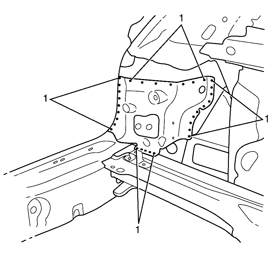
- Drill 8 mm (5/16 in) plug weld holes as necessary in the locations noted when disassembling.
- Clean and prepare the mating surfaces of both parts of the body side panel assembly.
- Apply approved structural adhesive (1) GM6449G or equivalent to the mating surfaces between the tail lamp filler panel and the back body inner pillar panel.
- Weld the tail lamp filler panel to the vehicle (1). Apply additional welds spaced every 32 mm (1¼ in) to the joint between the tail lamp filler panel and back body inner pillar panel.
- Apply the sealers and anti-corrosion materials to the repair area, as necessary. Refer to Anti-Corrosion Treatment and Repair.
- Paint the repaired area. Refer to Basecoat/Clearcoat Paint Systems.
- Install the tail lamp. Refer to Tail Lamp Assembly and /or Backup, Sidemarker, Stop, Turn Signal Bulb Replacement.
- Install the rear bumper fascia. Refer to Rear Bumper Fascia Replacement.
- Install the liftgate. Refer to Liftgate Replacement.
- Install the battery tray. Refer to Battery Tray Replacement.
- Install the battery. Refer to Battery Replacement.
- Install the quarter inner trim finish panel. Refer to Quarter Inner Trim Finish Panel Replacement.
- Install the liftgate weatherstrip. Refer to Liftgate Weatherstrip Replacement.
- Install the load floor front panel carpet. Refer to Load Floor Front Panel Carpet Replacement.
- Install the load floor stationary panel carpet. Refer to Load Floor Stationary Panel Carpet Replacement.
- Install the rear compartment floor panel carpet. Refer to Rear Compartment Floor Panel Carpet Replacement.
- Install the rear end trim finish panel. Refer to Rear End Trim Finish Panel Replacement.
- Connect the negative battery cable. Refer to Battery Negative Cable Disconnection and Connection.
- Enable the SIR system. Refer to SIR Disabling and Enabling.
Important: Spot welding is the preferred method for attaching panels and should be used whenever possible. A plug weld should only be performed where spot welding is not possible.
Important: If the location of the original plug weld holes cannot be determined, or if structural weld-thru adhesive is present, space the plug weld holes every 32 mm (1¼ in).
Important: Ensure that all factory welds are replaced in their original locations.
Important: Ensure that all structural adhesives and sealers are replaced in their original locations.
Important: Follow the adhesive manufacturer's instructions during the assembly process. Heat must be applied as per the manufacturer's specifications to cure the adhesives and to expand the sealing baffles.
Important: Secondary sealer must be applied to the perimeter of all flanges. Secondary sealer must be applied to all welds/joints that were originally covered by secondary sealer.

Important: As the tail lamp filler panel is installed to the vehicle, structural adhesive should be visible on the outside edges of both surfaces (squeezed out when pushed together).

