GM Service Manual Online
For 1990-2009 cars only

Certain vehicles may be equipped with a Secondary Air Injection (AIR) System. This system is used to lower tail pipe emissions on start-up. The PCM grounds the AIR pump relay control circuit, which energizes the AIR pump. The PCM also grounds the AIR Solenoid Valve control circuit, which energizes the AIR Solenoid Valve. The PCM enables both circuits when AIR system operation is desired. DTC P0412 applies to the AIR solenoid control circuit. DTC P0418 applies to the AIR pump relay control circuit. DTC P0410 sets if an air flow problem is detected.
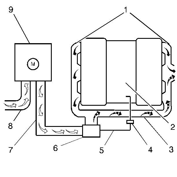
AIR System (If Equipped)


Object Number: 329101  Size: SH
(1)Exhaust Manifold
(2)Intake Manifold
(3)Exhaust Crossover Pipe
(4)Vacuum Check Valve
(5)Vacuum Supply Hose to the AIR Solenoid Valve
(6)AIR Solenoid Valve
(7)AIR Pipe (Pump to Solenoid Valve)
(8)Fresh Air Supply Hose
(9)AIR Pump

The PCM turns ON the AIR system during startup when engine coolant temperature is between 10°C (50°F) and 110°C (230°F). When ECT is above 80°C (176°F) at start up, AIR system operation will be delayed approximately 65 seconds. The AIR pump will operate for approximately 60 seconds. When the PCM turns the AIR pump OFF, it also de-energizes the AIR Solenoid Valve. The closed AIR Solenoid Valve prevents air from being drawn into the exhaust and also prevents the backflow of exhaust into the AIR System.

Refer to DTC P0410 Secondary Air Injection (AIR) System for enabling and disabling criteria.

Results of Incorrect Operation

If no air (oxygen) flow enters the exhaust stream, HC and CO emission levels will be too high.

Air flowing at all times could increase temperature of the warm up 3-way catalytic converter.

AIR Pump

The AIR pump is a regenerative turbine type which is permanently lubricated and requires no periodic maintenance.

The engine should be at normal operating temperature in neutral at idle. Using the scan tool enable the AIR system. Select HO2S Sensor 1on the scan tool. The HO2S voltage should remain under 350 mV because air is being added to the exhaust. If the HO2S voltage remains low during the Output Test, the AIR pump and AIR solenoid valve are operating satisfactorily. If the HO2S voltage does not remain low when the AIR system is enabled, inspect for the following:

    • A malfunctioning AIR pump or relay.
    • A malfunctioning AIR solenoid valve assembly.
    • A problem with the vacuum supply to the AIR solenoid valve.
    • AIR pump for proper mounting.

Refer to the appropriate DTC for diagnosis of the AIR system.

Hoses and Pipes

Inspect all AIR system pipes and hoses for the following:

    • Loose connections, and proper routing.
    • Component deterioration or damage.