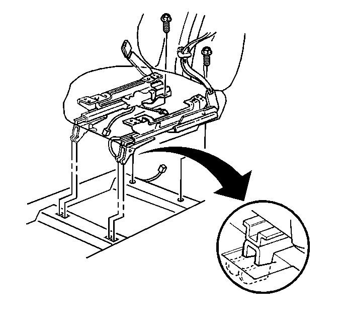
The following components
secure the front seats to the floor pan:
| • | Two front hook attachments |
| • | Two rear bolts installed to nuts that are welded to the floor
pan |

The manually operated
two-way front adjusters provide only fore and aft movement of the seat. The
seat adjuster handle is located on the front side of the seat. When
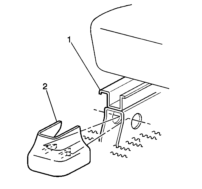
the seat adjuster handle is pulled up, the seat adjusters (1)
unlock. This action permits travel of the seat. When the seat is in
the desired position, and the seat adjuster handle is released, the
seat locks into place.

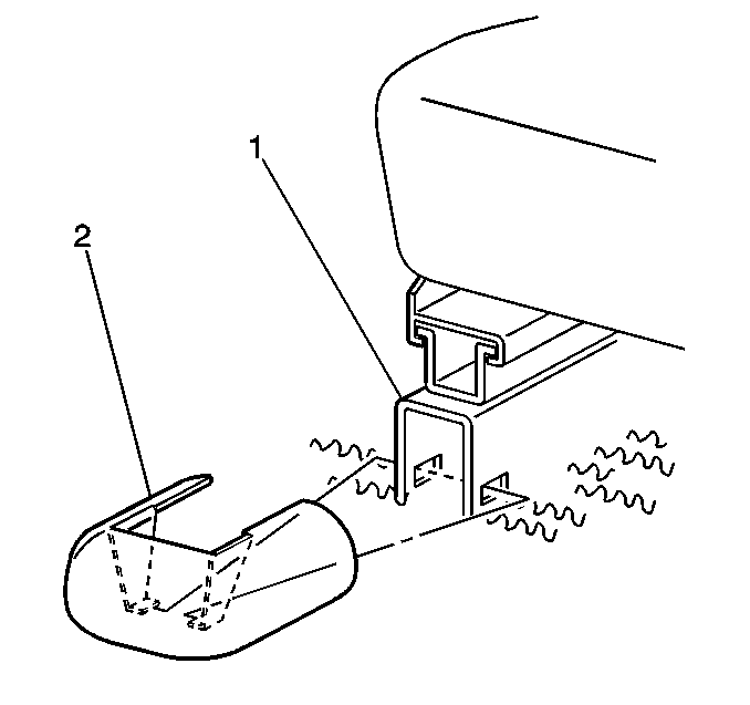
The power operated six-way
seat adjuster (1) (driver's side only) is activated by three motors.
These motors possess the following characteristics:
| • | Permanent magnet motors |
| • | Built-in circuit breaker |
A switch mounted on the seat cushion outer trim panel energizes the
motors.
The three motors drive the following components:
| • | A front vertical actuator |
| • | A rear vertical actuator |
When the adjusters reach the limit of travel, torque is absorbed through
the rubber mounted grommets. The grommets are located between the motor and
the support. The circuit provides an overload relay if excessive
torque is applied to the motor.
Removal Procedure

- Remove the seat adjuster
covers (2). The covers snap to the seat adjusters in the front and
rear.

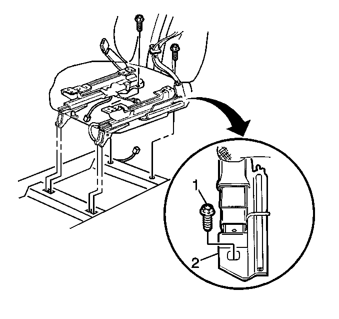
- Position the front seat
forward in order to gain access to the seat adjuster attaching bolts (1).
- Remove the seat adjuster attaching bolts (1).
- Disconnect the seat belt wiring harness (driver's side only).
- Disconnect the power seat electrical connector, if equipped, (driver's
side only).
- Remove the front seat. Manually tilt the seat forward in order
to disengage the hooks from the floor pan.
Installation Procedure
- Install the front seat. Manually tilt the seat forward in order
to engage the hooks to the floor pan.
- Connect the power seat electrical connector, if equipped, (driver's
side only).
- Connect the seat belt wiring harness (driver's side only).

- Position the front seat
forward in order to gain access to the seat adjuster attaching bolts (1).
Notice: Use the correct fastener in the correct location. Replacement fasteners
must be the correct part number for that application. Fasteners requiring
replacement or fasteners requiring the use of thread locking compound or sealant
are identified in the service procedure. Do not use paints, lubricants, or
corrosion inhibitors on fasteners or fastener joint surfaces unless specified.
These coatings affect fastener torque and joint clamping force and may damage
the fastener. Use the correct tightening sequence and specifications when
installing fasteners in order to avoid damage to parts and systems.
- Install the seat
adjuster bolts (1).
Tighten
Tighten the seat adjuster bolts (1) to 40 N·m (30 lb ft).
- Install the adjuster covers. Ensure that the units lock into place.


