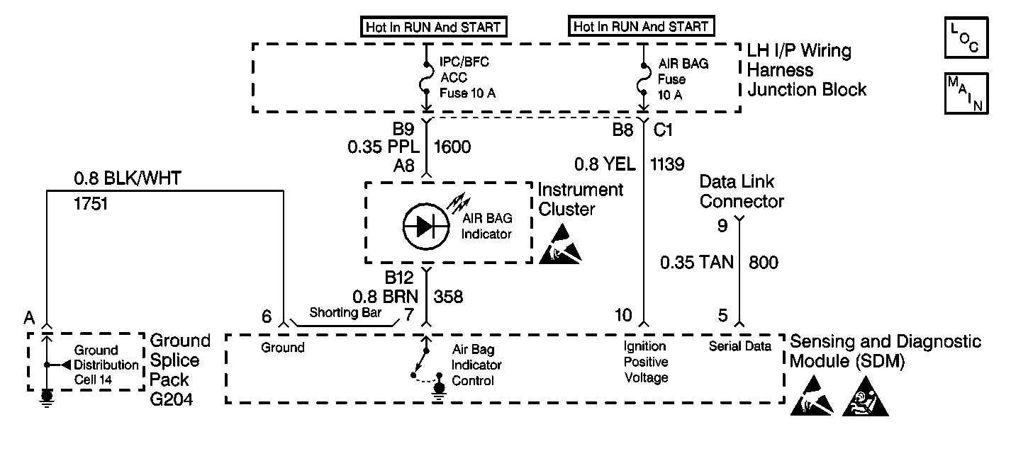
Circuit Description
When the ignition switch is first turned to RUN, the IPC/BFC Fuse applies battery voltage to the AIR BAG warning lamp that is connected to inflatable restraint indicator, terminal 7. The air bag fuse applies battery voltage to the IGNITION 1 input, terminal 10. The inflatable restraint Sensing and Diagnostic Module (SDM) responds by flashing the AIR BAG warning lamp 7 times.
Test Description
The numbers below refer to the step numbers on the diagnostic table:
-
This determines whether the malfunction is in the inflatable restraint sensing and diagnostic module (SDM) circuitry or in the instrument cluster power feed circuitry.
-
This determines whether voltage is present in the warning lamp circuit.
-
This isolates CKT 358 and checks for a short in CKT 358 to B+.
-
This determines if the malfunction is in the instrument cluster connector.
-
This determines if the open is due to a bad LED.
-
This tests whether power is available to the instrument cluster power feed circuit.
-
This tests for a short from the instrument cluster power feed circuit to ground.
-
This determines whether the short to ground is due to a short in the wiring or internal to the instrument cluster.
-
This determines if the malfunction is in the instrument cluster connector.
-
This determines whether the malfunction is due to an open power feed circuit from the IPC/BFC Fuse.
Step | Action | Value(s) | Yes | No |
|---|---|---|---|---|
1 | Was the SIR Diagnostic System Check performed? | -- | ||
Does the BRAKE indicator light? | -- | |||
Is the voltage more than the specified value? | 10.0 V | |||
Is the voltage less than the specified value? | 1.0 V | Go to Integrity Check | ||
5 |
Are the repairs complete? | -- | -- | |
Is the connector damaged or corroded? | -- | |||
7 | Repair the instrument cluster harness connector. Refer to Connector Repairs in Wiring Systems. Are the repairs complete? | -- | -- | |
Measure the resistance from the instrument cluster harness connector terminal C15 to the SDM harness connector terminal 7. Is the resistance reading within the specified values? | 0-5 ohms | |||
9 |
Are the repairs complete? | -- | -- | |
10 | Service the instrument cluster. Refer to Instrument Cluster Replacement in Instrument Panel, Gages and Console. Are the repairs complete? | -- | -- | |
Is the fuse good? | -- | |||
Is the fuse good? | -- | |||
Is the fuse good? | -- | |||
14 |
Are the repairs complete? | -- | -- | |
15 |
Are the repairs complete? | -- | -- | |
16 | Install the IPC/BFC Fuse. Are the repairs complete? | -- | -- | |
Is the connector damaged or corroded? | -- | |||
18 | Repair the instrument cluster harness connector. Refer to Connector Repairs in Wiring Systems. Are the repairs complete? | -- | -- | |
Measure the resistance between the instrument cluster harness connector terminal B12 to each terminal of the IPC/BFC Fuse fuseholder. Is either reading within the specified values? | 0-5 ohms | |||
20 |
Are the repairs complete? | -- | -- | |
21 |
Are the repairs complete? | -- | -- | |
22 | Reconnect all the SIR system components, make sure all the components are properly mounted. Have all the SIR components been reconnected and properly mounted? | -- | -- |
