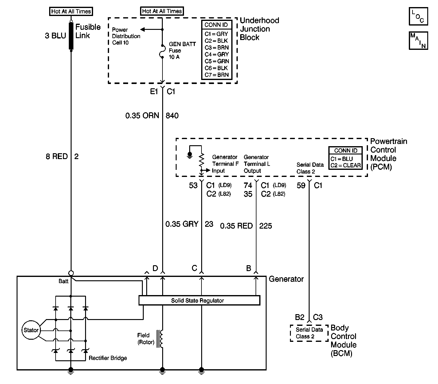
Circuit Description
This DTC determines if a fault exists that renders the generator L-terminal continuously high.
Conditions for Setting the DTC
| • | All of the following conditions must be met: |
| • | Ignition 1 is active and the engine is OFF. |
| • | The powertrain control module (PCM) is sending the L terminal high class 2 serial data message for 30 seconds. |
Action Taken When the DTC Sets
| • | The body control module (BCM) stores DTC B1488 in memory. |
| • | The volts indicator will illuminate. |
Conditions for Clearing the DTC
| • | The BCM goes to sleep. The controller reinitializes with the fault cleared. |
| • | Use the scan tool. |
Diagnostic Aids
| • | When the engine is OFF, inspect for a short to the battery on the 225 circuit. |
| • | If the DTC is a history DTC, the problem may be intermittent. Perform the tests shown while wiggling the wiring and connectors. This can often cause the malfunction to appear. |
Test Description
The numbers listed below refer to the numbers on the diagnostic table.
-
This step determines if the L-terminal is actually being held low.
-
This step determines if CKT 225 is open.
-
This step determines if CKT 225 has a short to ground condition.
-
This step determines if the Powertrain Control Module (PCM) is reading the L-terminal status equal to the J 39200 DMM voltage readings.
Step | Action | Value(s) | Yes | No |
|---|---|---|---|---|
|
Important: A short to ground will cause an open fuse(s). Before performing this diagnostic procedure, inspect the fuse(s) for an open. | ||||
1 | Was the Body Control Module (BCM) System Check performed? | -- | Go to Step 2 | |
Is the measured voltage equal to the specified value? | 0V | Go to Step 5 | Go to Step 3 | |
Is the measured resistance within the specified range? | 0-2ohms | Go to Step 4 | Go to Step 7 | |
Is the measured voltage equal to the specified value? | 4.5-5.5V | Go to Step 6 | Go to Step 8 | |
Use the scan tool in order to read the PCM L-terminal status. Is the scan tool reading equal to the specified value? | Inactive | Go to Step 9 | Go to Step 8 | |
6 | Replace the generator. Refer to Generator Replacement in Engine Electrical. Is the repair complete? | -- | Go to Step 9 | -- |
7 | Repair the open in CKT 225 between the PCM connector C2 terminal 61 (connector C1 terminal 74 for LD9) and the generator connector terminal B. Refer to Wiring Repairs in Wiring Systems. Is the circuit repair complete? | -- | Go to Step 9 | -- |
8 | Replace the PCM. Refer to Powertrain Control Module Replacement or Powertrain Control Module Replacement/Programming in Engine Controls. Is the repair complete? | -- | Go to Step 9 | -- |
9 | Clear the DTCs from the memory. Are the DTCs cleared from the memory? | -- | -- | |
