Removal Procedure
- Disconnect the negative battery cable.
- Open the IPC door.
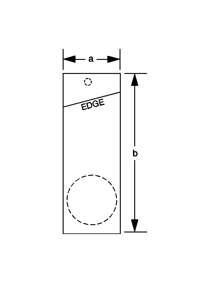
- Make a photocopy of the template shown in the illustration above.
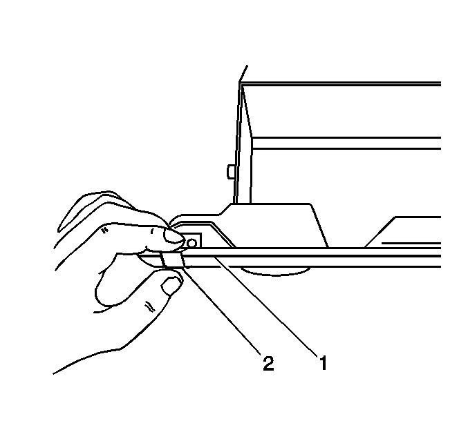
- Place the template copy over the lock cylinder bezel and align the "EDGE" on the template (2) with the edge of the face of the IPC door (1).
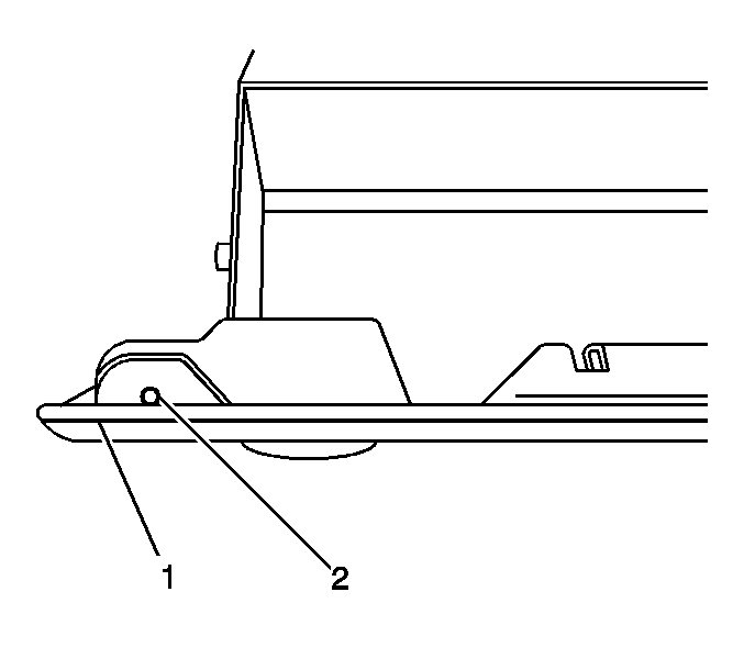
- Fold the template (2) to the contour of the IPC door (1). Mark the position of the center line of the small hole on the template to the IPC door. This position should be 1.6 mm (1/16 in) forward of the edge of the IPC door face, and in line with the key slot in the lock cylinder.
- Remove the template.
- While lifting up on the IPC door handle, drill a 3.2 mm (1/8 in) hole at the point (2) which you marked.
- Insert the key into the IPC door lock cylinder.
- Lift up on the IPC door handle and insert a 1/16-inch hex head wrench, or equivalent, into the drilled hole in order to depress the lock cylinder retainer. The retainer is spring-loaded and is a part of the lock cylinder.
- Turn the key clockwise to the 3 o'clock position.
- Pull on the key to remove the lock cylinder from the IPC door.
Important: When photocopying the template in step 3, be aware that some printed copies may not be an exact copy of the original. Some copiers may produce a copy slightly smaller or larger than the original. This condition can also occur when printing the template from SI2000. Prior to performing any of the steps listed below, verify that the copy made is to the original template size. This is done by measuring the width (a), and the length (b) on your printed copy. The width (a) should be 24 mm (15/16 in), and the length (b) should be 66 mm (2 5/8 in).

Caution: Unless directed otherwise, the ignition and start switch must be in the OFF or LOCK position, and all electrical loads must be OFF before servicing any electrical component. Disconnect the negative battery cable to prevent an electrical spark should a tool or equipment come in contact with an exposed electrical terminal. Failure to follow these precautions may result in personal injury and/or damage to the vehicle or its components.


Important: Position the drill so that the rearward edge of the hole is flush with the face edge of the IPC door.
Important: You MUST use the ignition key to properly remove the lock cylinder from the IPC door. If the ignition key or the key code is unavailable, replace the IPC door and the lock cylinder.
Installation Procedure
- Insert the lock cylinder into the IPC door in the 3 o'clock position.
- Rotate the key counterclockwise until you hear a snap in the 12 o'clock position.
- Inspect the IPC door lock cylinder for proper operation.
- Connect the negative battery cable.

Tighten
Tighten the cable bolt to 16 N·m (12 lb ft).
