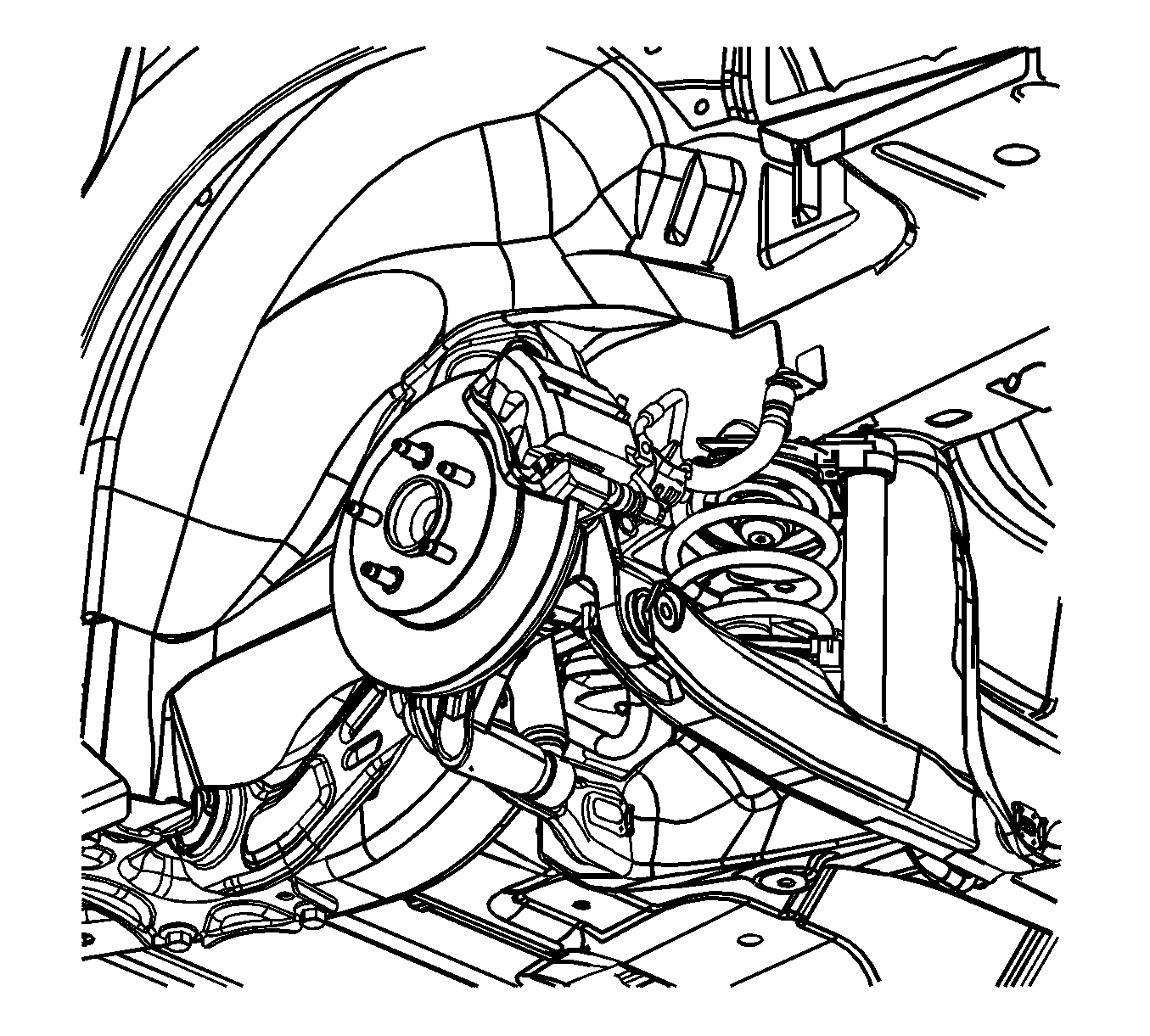
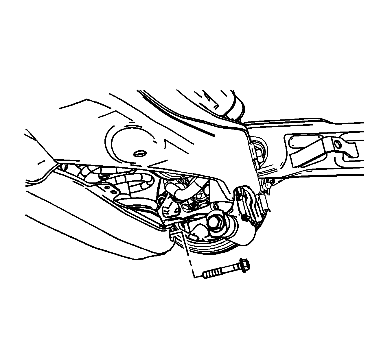
For 1990-2009 cars only
Removal Procedure
- Raise and support the vehicle. Refer to Lifting and Jacking the Vehicle in General Information.
- Remove the rear tire and wheel. Refer to Tire and Wheel Removal and Installation in Tires and Wheels.
- Use a OTC 204-167 compressor and OTC 204-167-01 adapter shoes or equivalent on vehicle spring compressor to compress the coil spring.
- Using a suitable jack stand, support the lower control arm.
- Remove the lower control arm to knuckle bolt, nut, and inboard fastener to the support.
- Use the jackstand in order to lower the lower control arm with the coil spring attached.
- Remove the coil spring from the lower control arm.
- Inspect the coil spring insulators for damage and replace as necessary.


Caution: To prevent personal injury and/or component damage, use the proper tools to support the lower control arm when removing the coil spring. The coil spring is under extreme pressure and can become a projectile should the spring separate from the lower control arm before all of the tension is relieved.
Installation Procedure
- Position the spring on the lower control arm.
- Use the jack stand to raise the lower control arm into position.
- Install the lower control arm to knuckle bolt and nut.
- Remove the OTC 204-167 or equivalent on vehicle spring compressor to compress the coil spring.
- Remove the jack stand.
- Install the rear tire and wheel. Refer to Tire and Wheel Removal and Installation in Tires and Wheels.
- Lower the vehicle.
Notice: Refer to Fastener Notice in the Preface section.

Tighten
Tighten the bolt and nut to 60 N·m (44 lb ft) plus an additional 60 degrees.

