Rail Sectioning Rear Side Underbody 1/3 Rail
Removal Procedure
- Disable the SIR system. Refer to SIR Disabling and Enabling in SIR.
- Disconnect the negative battery cable. Refer to Battery Negative Cable Disconnection and Connection in Engine Electrical.
- Remove all of the related panels and the components.
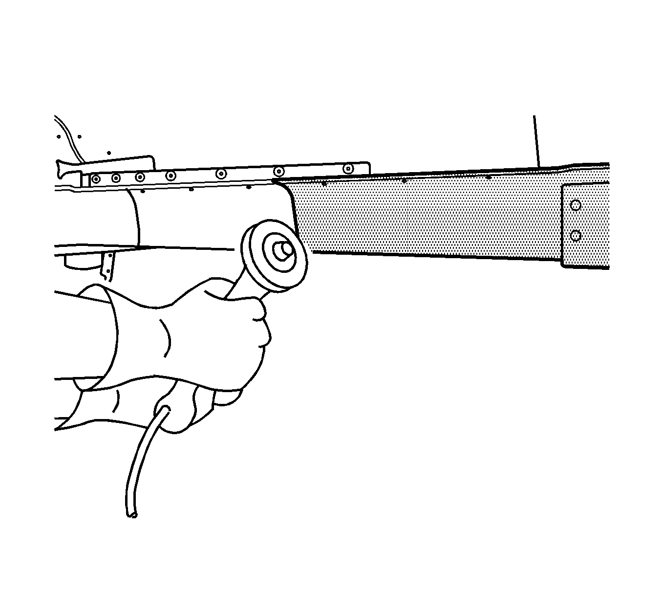
- Remove the sealers and anti-corrosion materials from the repair area, as necessary. Refer to Anti-Corrosion Treatment and Repair in Paint and Coatings.
- Repair as much of the damage as possible. Refer to Dimensions - Body .
- Locate the die mark on the outer lower surface of the rear rail, rearward of the #5 bar.
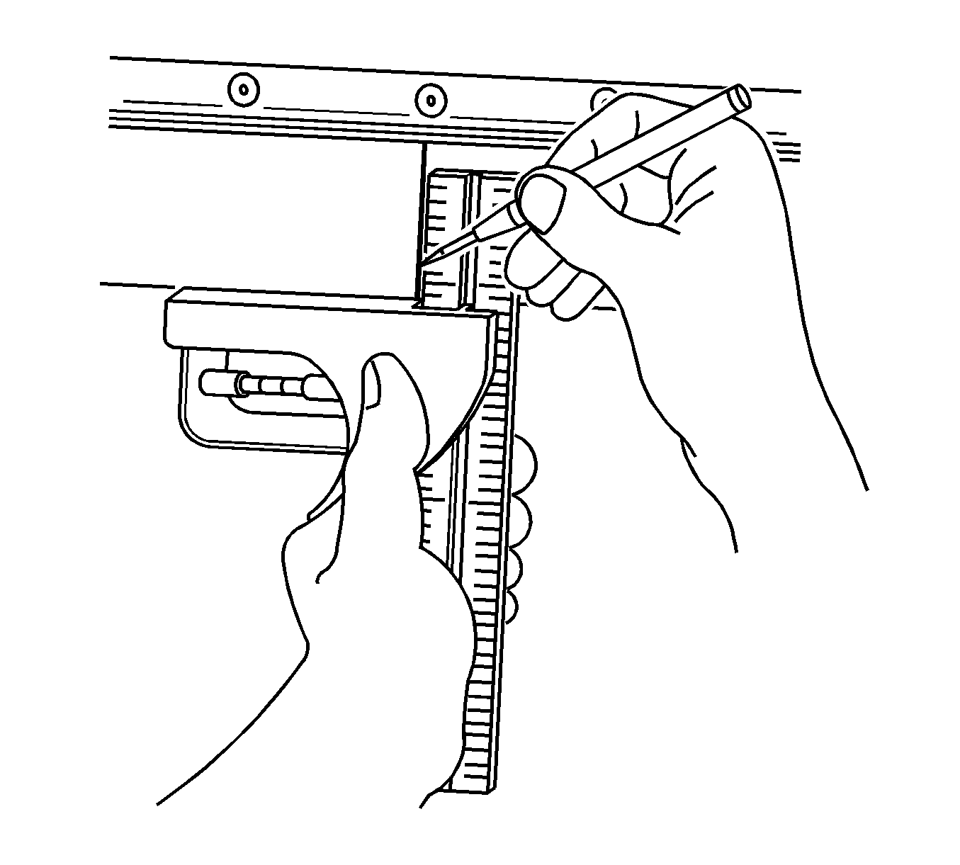
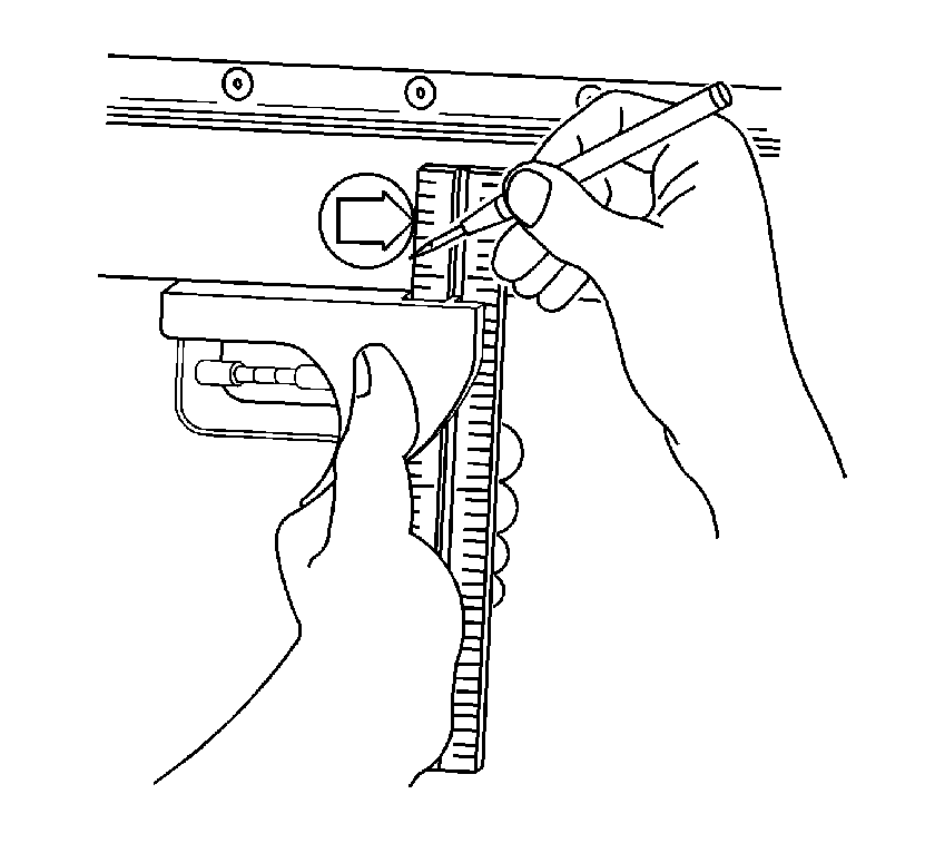
- Align a sliding square or similar tool to the line at the tip of the arrow in the die mark. Scribe a line across the rail.
- Use the same tool to transfer this scribed line onto the sides and the weld flanges of the rail.
- Cut at the marked location.
- Remove the damaged component from the vehicle.
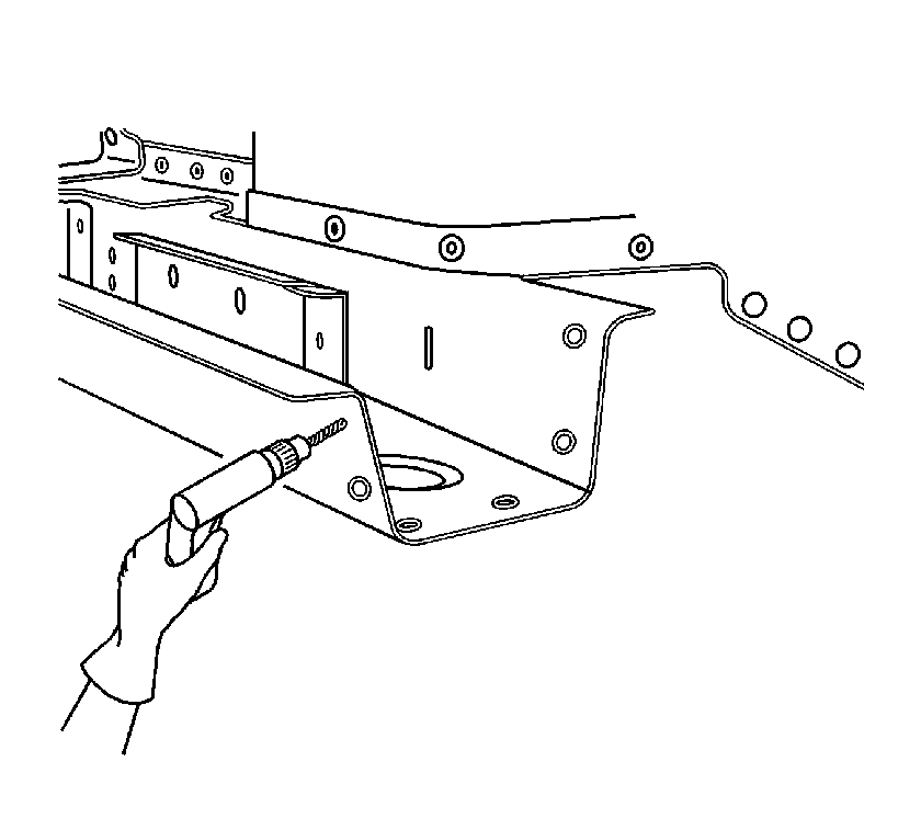
- Drill 2 8 mm (5/16 in) plug weld holes on each of the 3 sides of the rear rail. Position the center of the holes 10 mm (3/8 in) from the cut edge.
Caution: Refer to Approved Equipment for Collision Repair Caution in the Preface section.
Caution: Sectioning should be performed only in the recommended areas. Failure to do so may compromise the structural integrity of the vehicle and cause personal injury if the vehicle is in a collision.
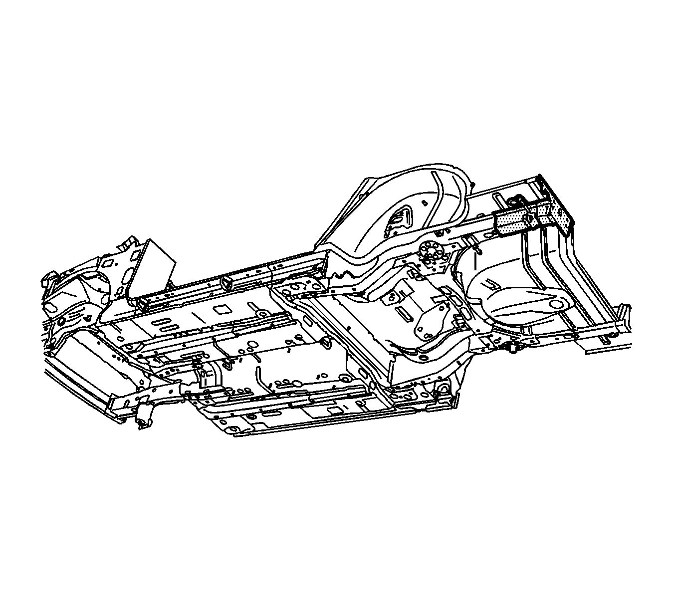
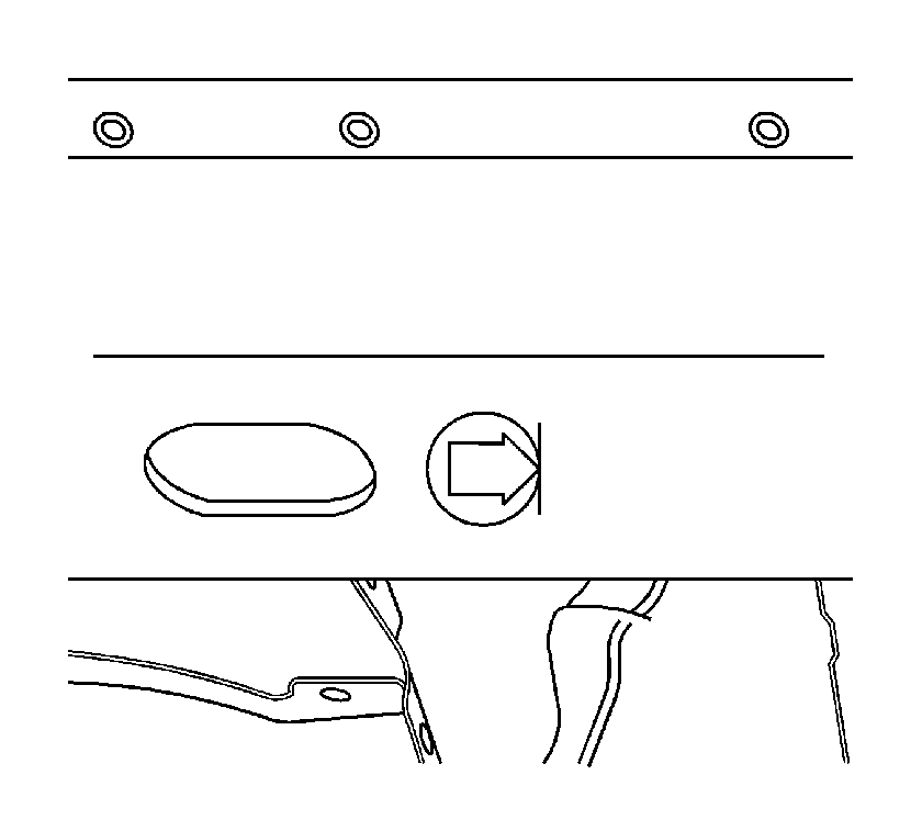
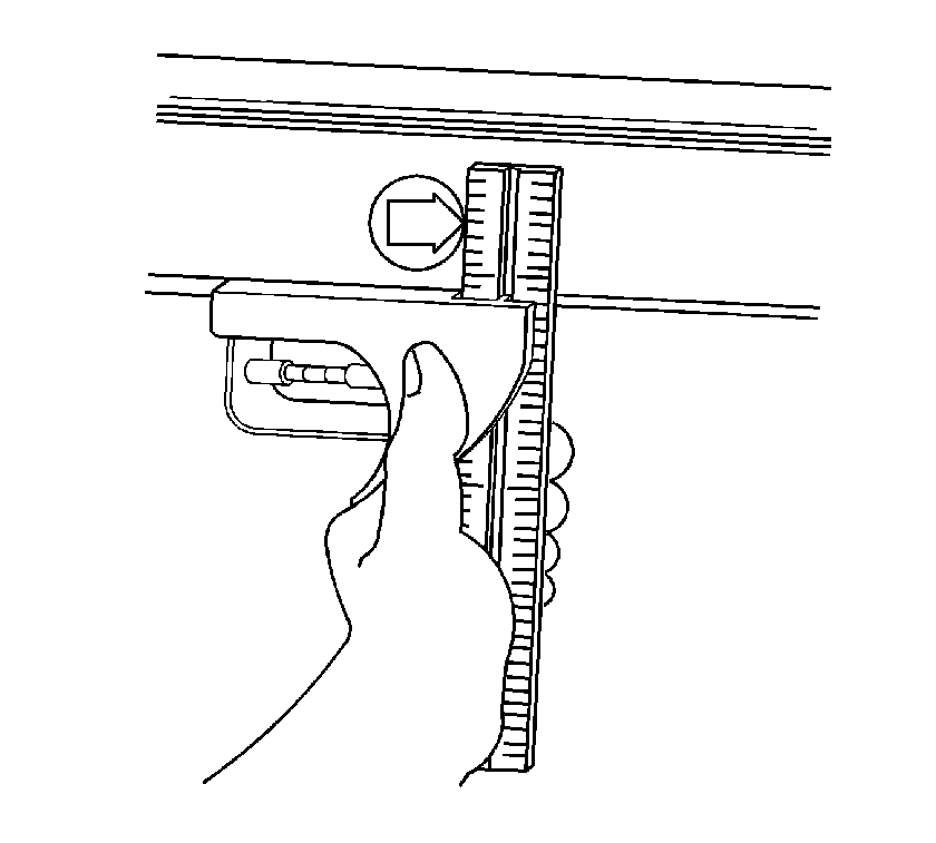
Important: Do not section the rail in any area other than the die mark location given.
Installation Procedure
- Locate the die marks on the service part rear rail.
- Align a sliding square or similar tool to the line at the tip of the arrow in the die mark and scribe a line across the rail.
- Use the same tool to transfer this scribed line onto the sides and the weld flanges of the rail.
- Place a mark forward, towards the rear of the arrow, 25 mm (1 in) from the scribed line on all 3 sides of the service rail.
- Use the tool to scribe a line on all 3 sides and weld flanges of the rail.
- Cut at the scribe line at the rear of the arrow.
- Remove the rear portion of the rail.
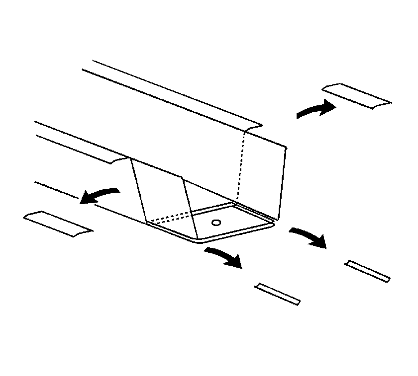
- Cut the upper outer flanges of the rear portion of the rear rail service part. Cut the flanges back to the first scribe line and remove the tabs.
- Cut the lower radius corners of the service part back to the first scribe line and remove the small corners.
- Bend the bottom side of the service part at the sectioning location inward slightly by aligning a vice grip flanging tool or similar tool at the first scribed line.
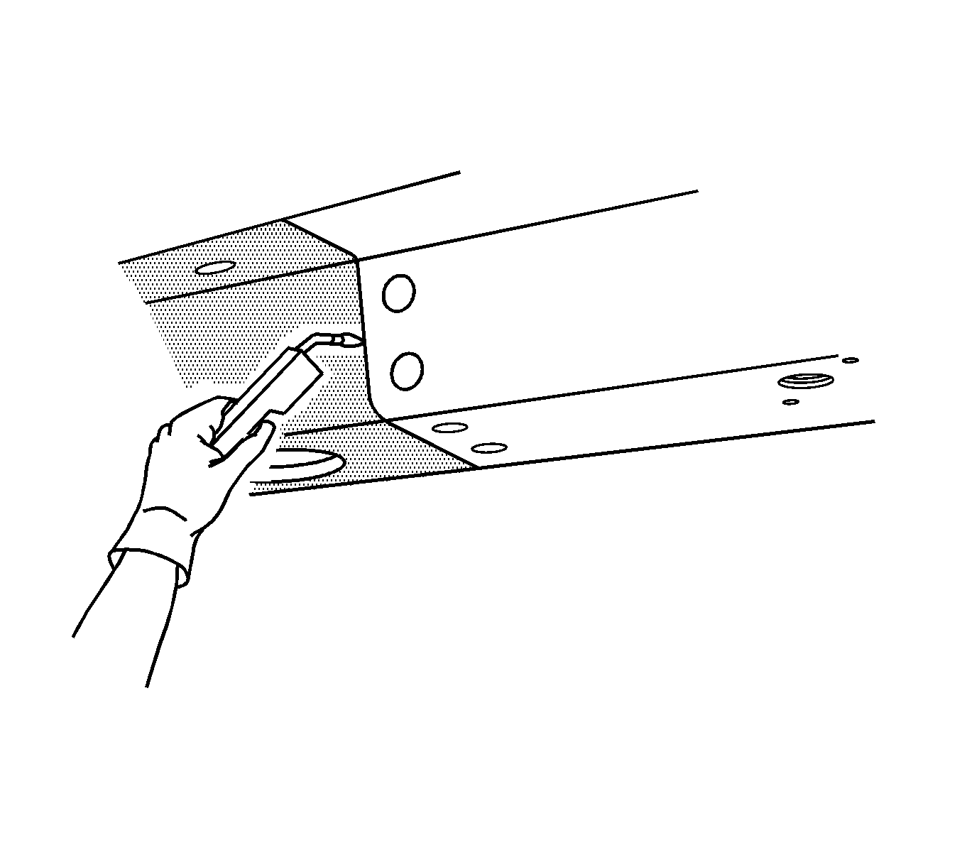
- Prepare the sectioning area of the rear rail for welding.
- Apply 3M® Weld-Thru coating P/N 05916 or equivalent to all mating surfaces.
- Position the rear rail section using 3-dimensional measuring equipment. Clamp the rail section in place.
- Tack weld the part into position.
- Inspect the service rear rail for proper dimensions, using 3-dimensional measuring equipment.
- Plug weld at each 8 mm (5/16 in) plug weld hole location.
- Stitch weld along the entire sectioning joint. Make welds along the seam with 25 mm (1 in) gaps between. Weld the gaps.
- Clean and prepare the welded surfaces.
- Install all of the related panels and components.
- Apply the sealers and anti-corrosion materials to the repair area, as necessary. Refer to Anti-Corrosion Treatment and Repair in Paint and Coatings.
- Paint the repaired area. Refer to Anti-Corrosion Treatment and Repair in Paint and Coatings.
- Enable the SIR system. Refer to SIR Disabling and Enabling in SIR.
- Connect the negative battery cable. Refer to Battery Negative Cable Disconnection and Connection in Engine Electrical.




Rail Sectioning Rear Side Underbody 3/4 Rail
Removal Procedure
- Disable the SIR system. Refer to SIR Disabling and Enabling in SIR.
- Disconnect the negative battery cable. Refer to Battery Negative Cable Disconnection and Connection in Engine Electrical.
- Remove all related panels and components.
- Repair as much of the damaged area as possible. Refer to Dimensions - Body .
- Remove the sealers and anti-corrosion materials from the repair area, as necessary. Refer to Anti-Corrosion Treatment and Repair in Paint and Coatings.
- Remove the rear wheelhouse extension.
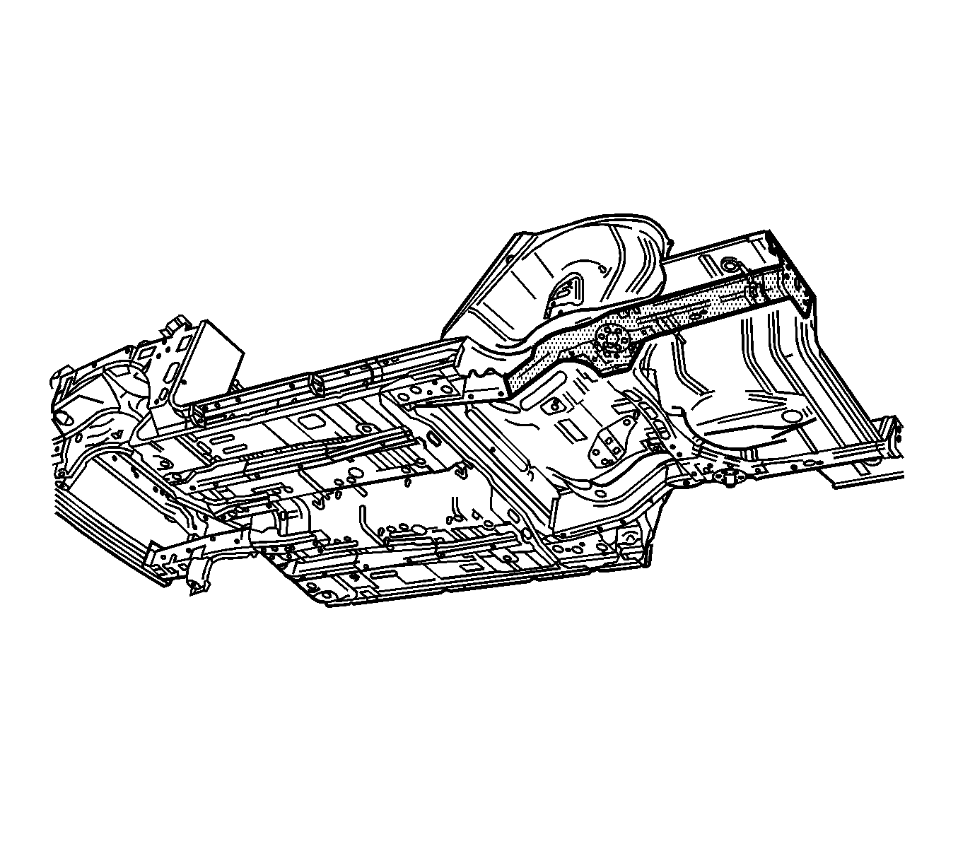
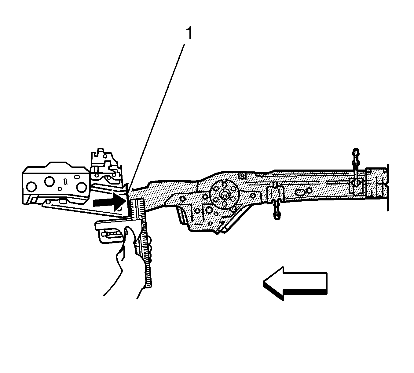
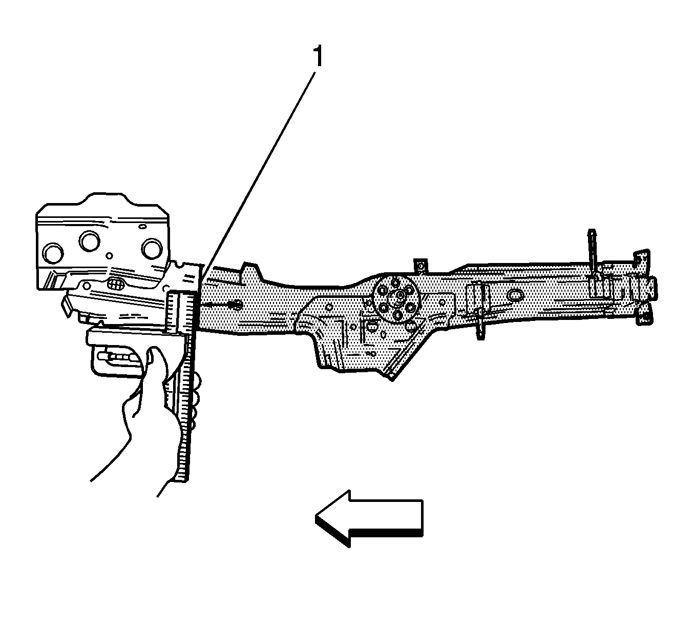
- Measure from the rear edge of the control arm attaching hole rearward 30 mm (1.2 in) (1). Align a sliding square or similar tool to the measured point. Scribe a line across the rail at the measured point.
- Use a sliding square to transfer the scribed line onto the sides and weld flanges of the rail.
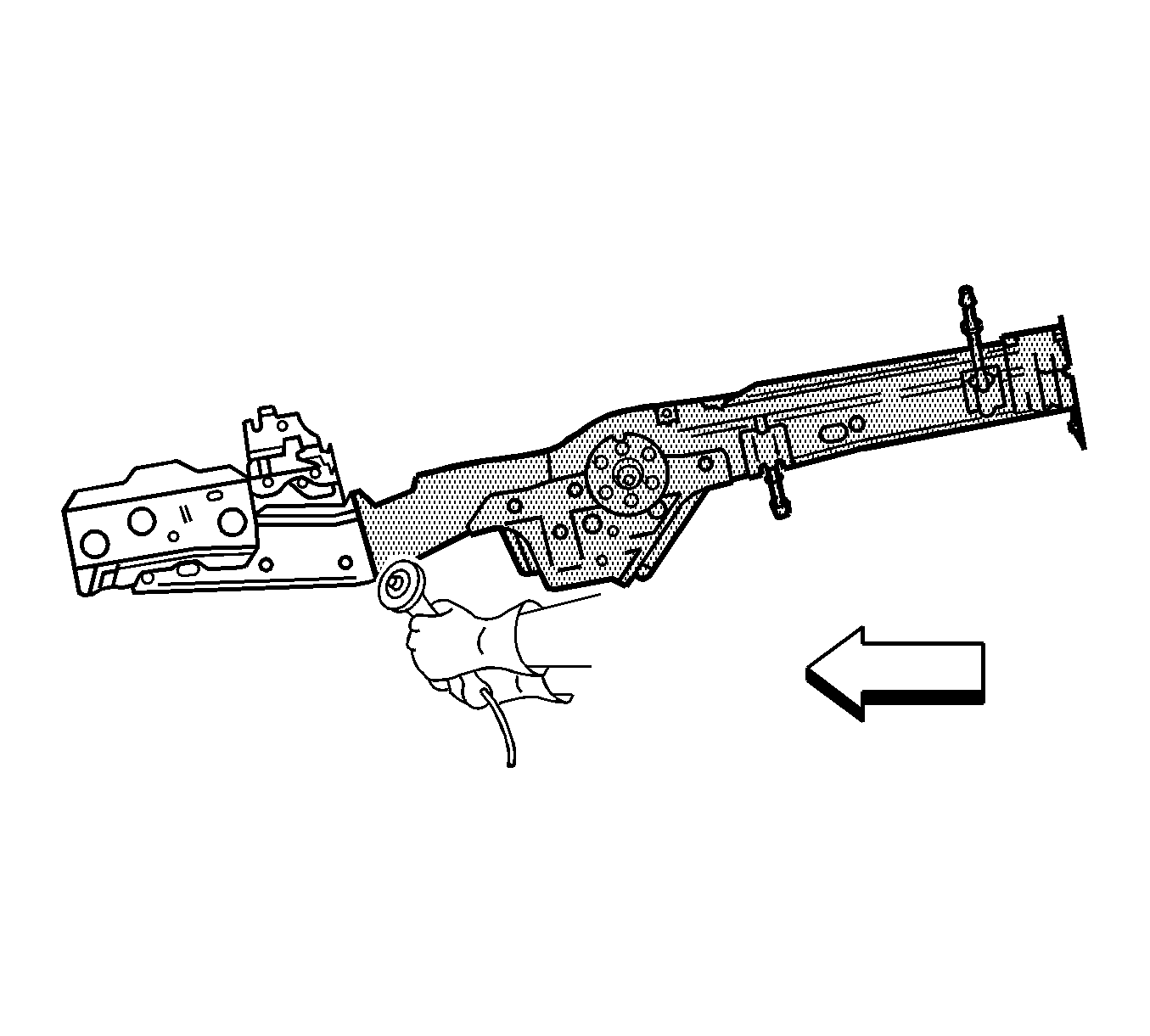
- Cut the rail at the marked location.
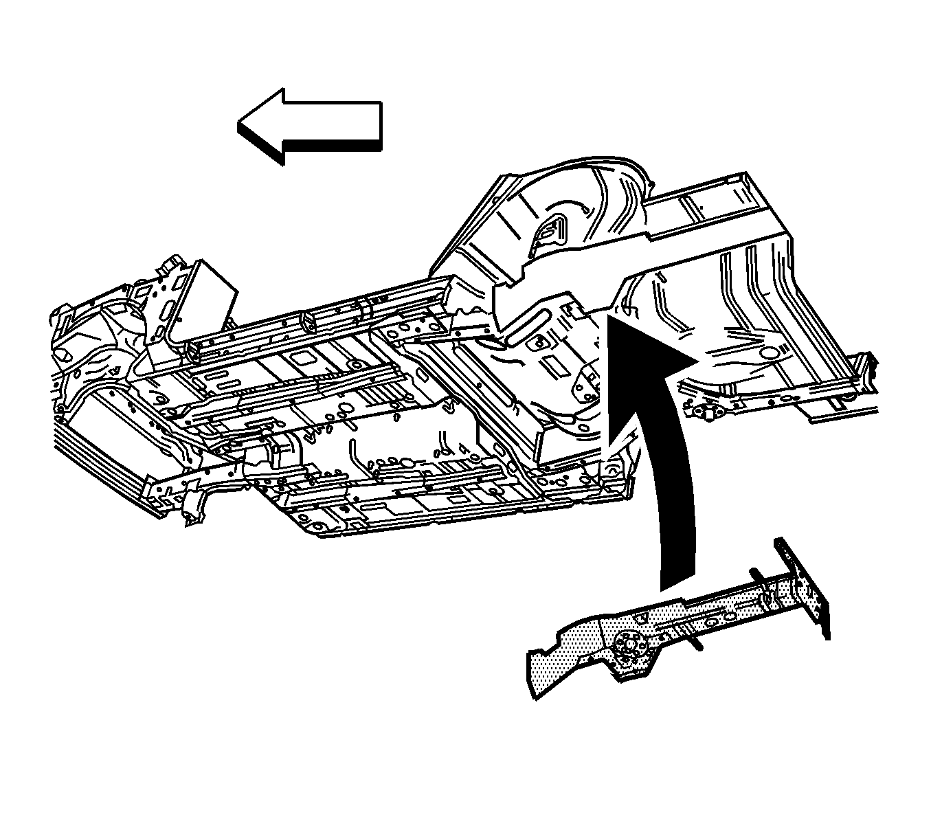
- Remove the damaged rail from the vehicle.
Caution: Refer to Approved Equipment for Collision Repair Caution in the Preface section.
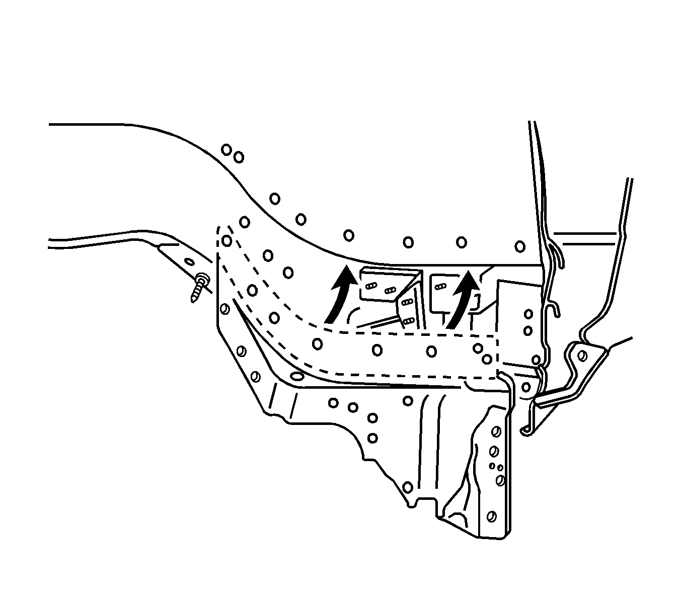
Important: There is a hidden weld under the wheelhouse.

Installation Procedure
- Remove the rear wheelhouse extension.
- Remove the bracket for the rear axle control arm.
- Drill out the spot welds.
- Measure from the rear edge of the control arm attaching hole forward (1) 90 mm (3.5 in) on the service part rear rail. Align a sliding square or similar tool to the measured point. Scribe a line across the rail at the measured point.
- Use a sliding square to transfer the scribed line onto the sides and weld flanges of the rail.
- Cut the rail at the scribed line.
- Remove the rear rail.
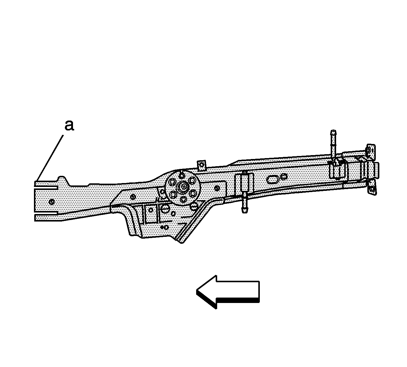
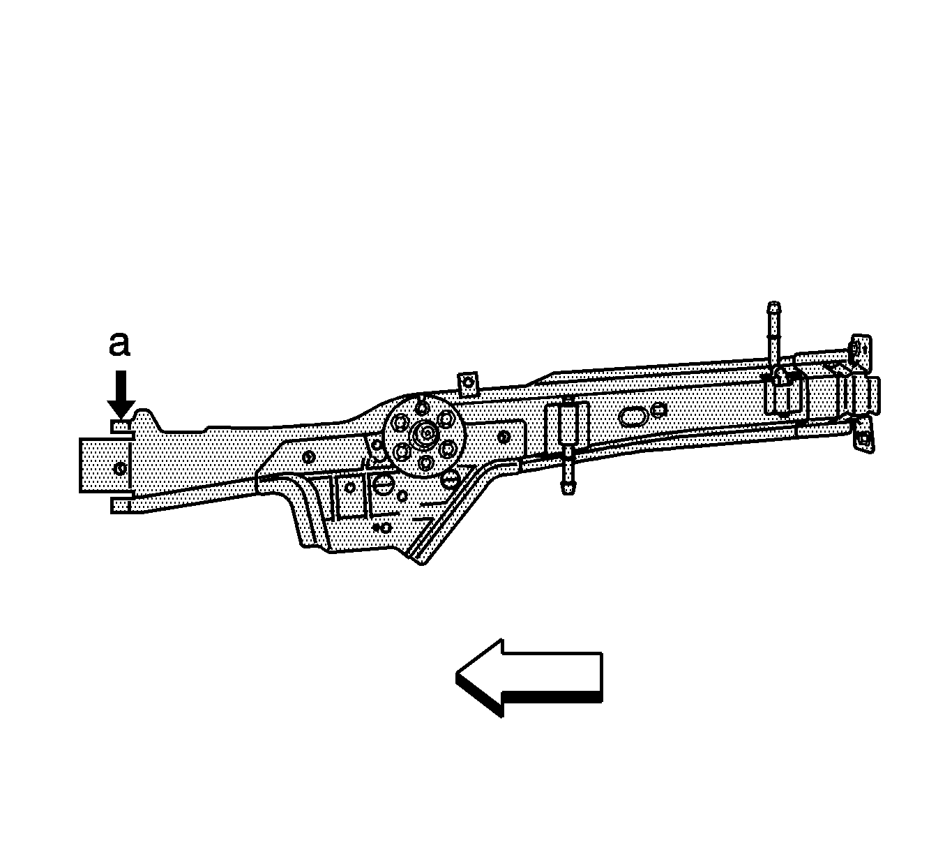
- Measure from the cut edge of the service rail (a) 110 mm (4.3 in) toward the rear of the vehicle. Cut a slot in the upper outer edges of the service rail.
- Measure from the cut edges of the rail (a) 70 mm (2.75 in). Cut the upper outer flanges of the rear rail service part. Remove the tabs.
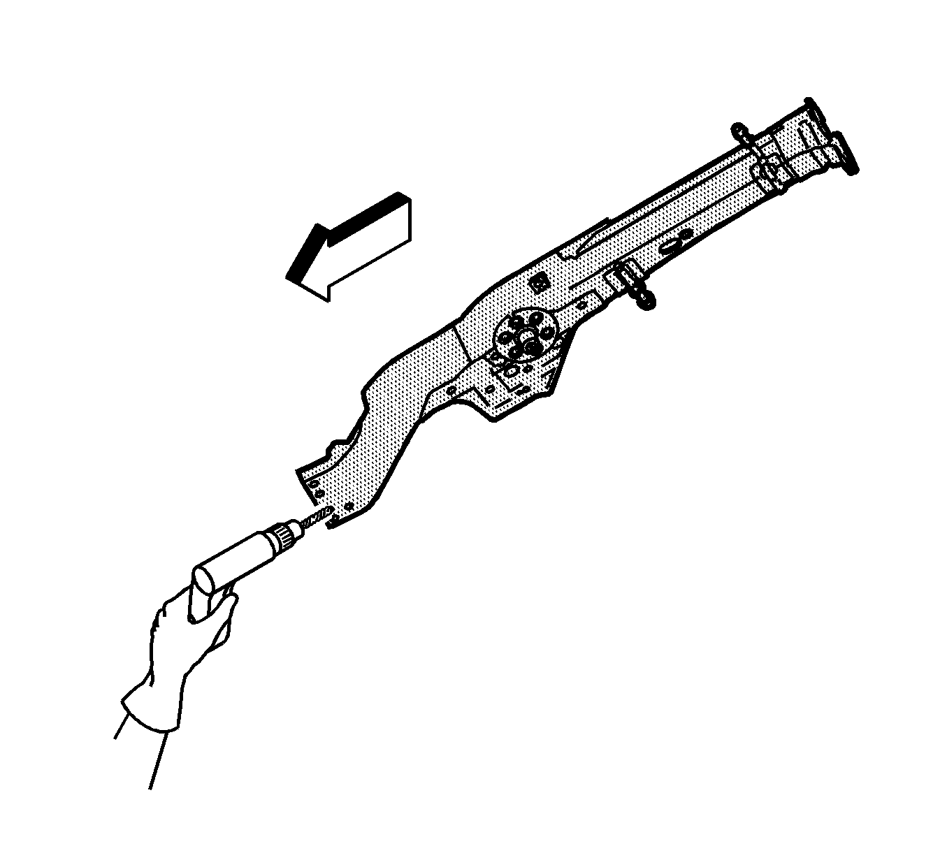
- Drill two 8 mm (5/16 in) plug weld holes on each of the 3 sides of the rear rail. Position the center of the holes 10 mm (3/8 in) from the cut edge.
- Prepare all mating surfaces for welding as necessary.
- Apply 3M Weld-Thru Coating P/N 05916 or equivalent to all mating surfaces.
- Position the rear rail section using 3-dimensional measuring equipment. The service rail will overlap the existing rail in the vehicle. Clamp the rail section in place.
- Tack weld the part into position.
- Inspect the service rear rail for proper dimensions, using 3-dimensional measuring equipment.
- Plug weld accordingly at each plug weld hole location.
- Stitch weld along the entire sectioning joint. Make the welds along the seam with 25 mm (1 in) gaps between. Weld the gaps.
- Install the rear wheelhouse extension.
- Clean and prepare all of the welded surfaces.
- Install all of the related panels and components.
- Apply the sealers and anti-corrosion materials to the repair area, as necessary. Refer to Anti-Corrosion Treatment and Repair in Paint and Coatings.
- Paint the repaired area. Refer to Basecoat/Clearcoat Paint Systems in Paint and Coatings.
- Enable the SIR system. Refer to SIR Disabling and Enabling in SIR.
- Connect the negative battery cable. Refer to Battery Negative Cable Disconnection and Connection in Engine Electrical.
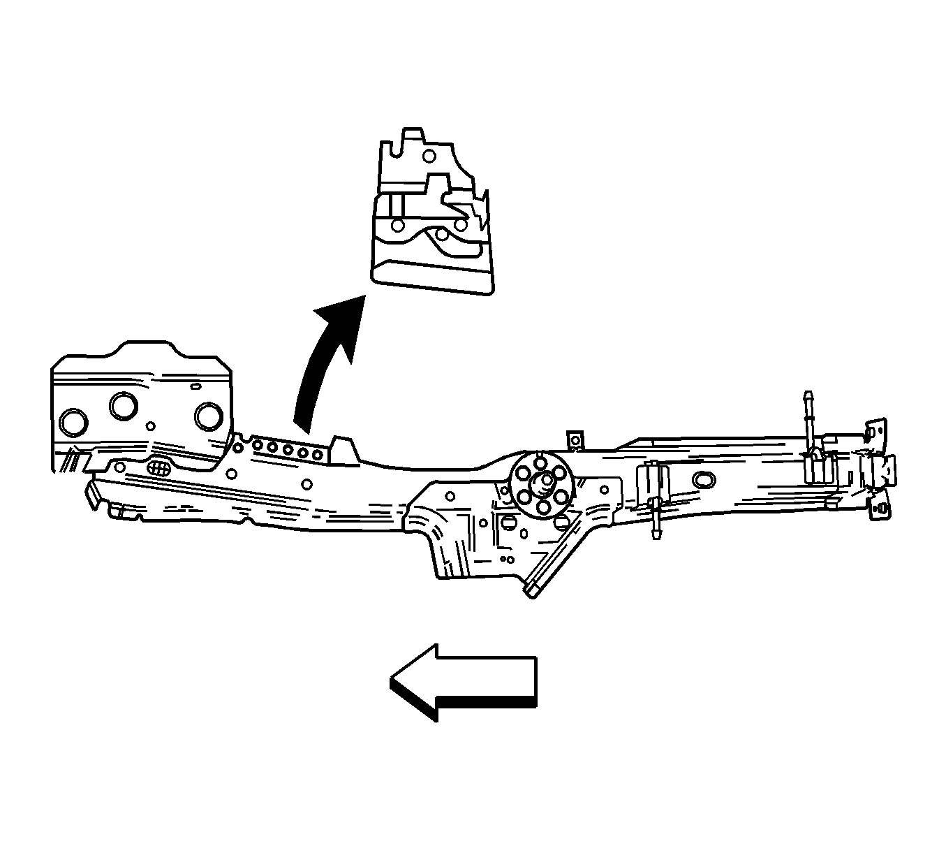
Important: The service part includes the rear wheelhouse extension and the filler rocker inner panel bracket for the rear axle control arm. You may not section the rear rail with the rear wheelhouse extension and the bracket for the rear axle control arm.


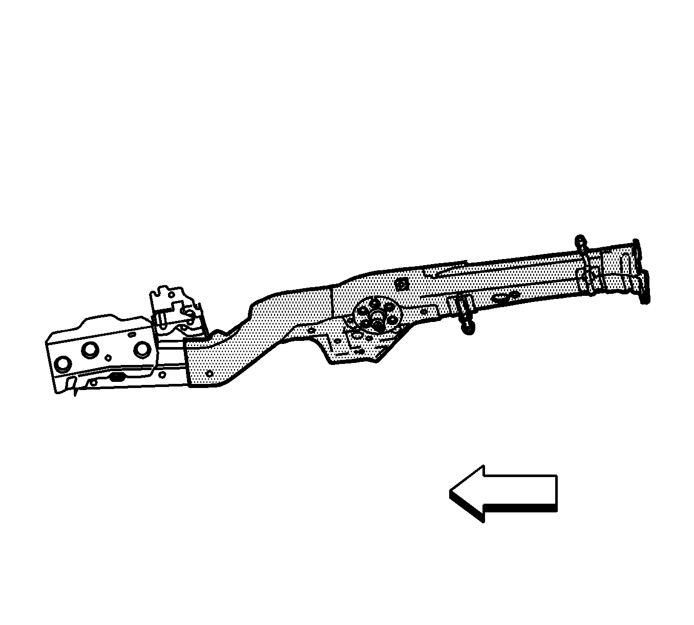
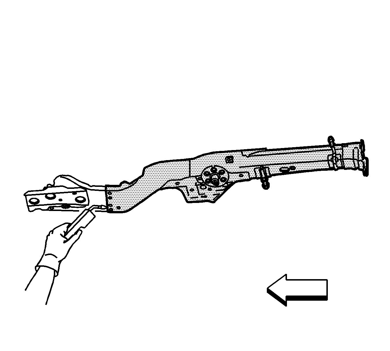

Rail Sectioning Rear Side Underbody Extended Sedan
Removal Procedure
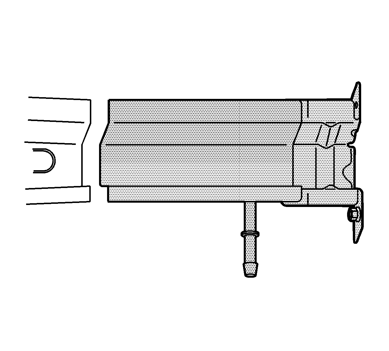
Sectioning procedures can be used to repair the rear rail if just the portion rearward of the crossbar is damaged. The assembly consists of the outer rail panel with the bumper mounting brackets attached and the shock mount with internal reinforcements.
Important: If damage exceeds the recommended area for sectioning and the rail cannot be straightened, the complete rail must be replaced.
- Remove all related panels and components.
- Visually inspect and restore as much of the damage as possible to factory specifications.
- Remove sealers and anti-corrosion materials as necessary.
- Locate, mark, and drill out all factory welds. Note the number and location of welds for installation of the service assembly.
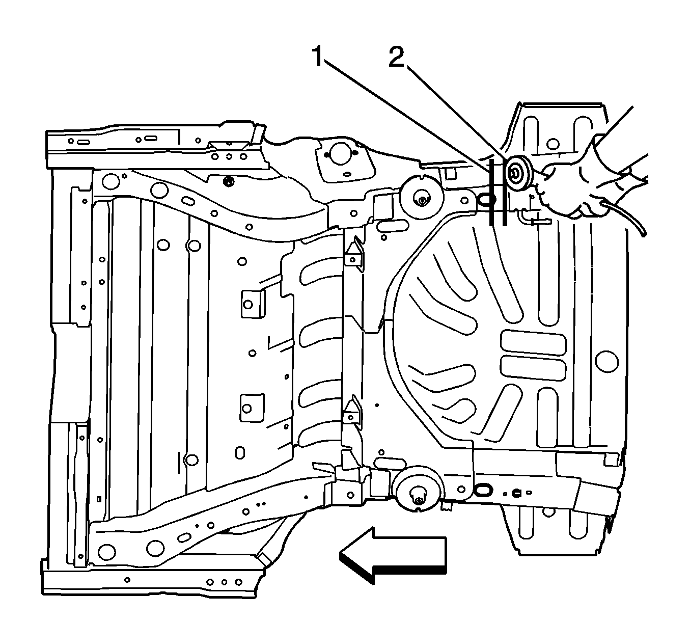
- Locate the rear edge shipping slot (1) 25 x 40 mm (1 x 1.6 in) in the rear rail.
- Use a straight edge to scribe a line around the rail.
- Mark and cut the damaged rail (2) 30 mm (1.8 in) rearward of the shipping slot.
- Remove the damaged section of the rail.
Installation Procedure
- Locate the rearward shipping slot on the service part.
- At the rear edge of the shipping slot, mark and cut the rail. This is the service part.
- Cut the service part and discard the unused portion.
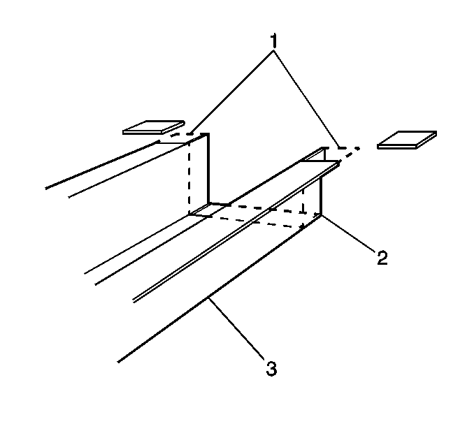
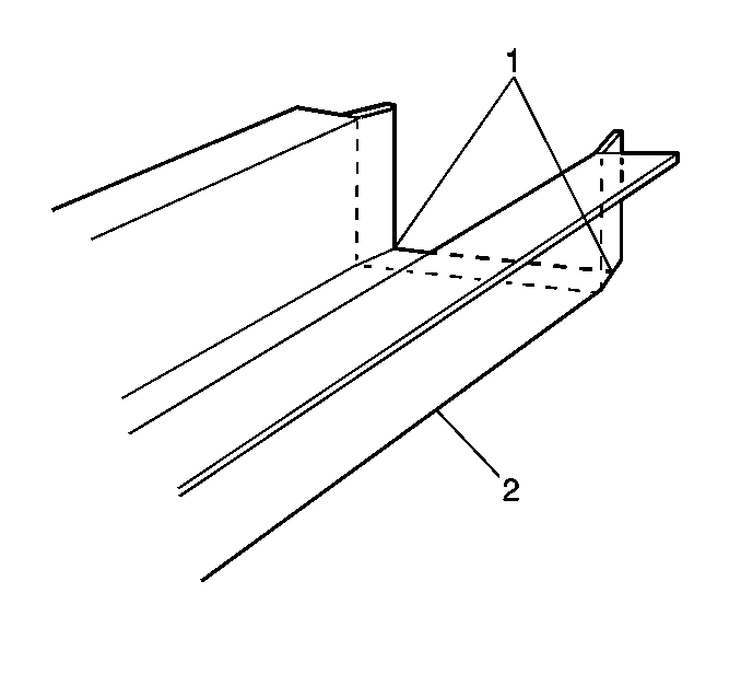
- Cut and remove 30 mm (1 3/16 in) from the flanges on either side (1) of the service rail (3) to create 30 mm (1 3/16 in) tabs.
- Cut 5 mm (3/16 in) wide gaps in the bottom corners (2).
- Step the tabs inward to allow the service section (2) to fit inside of the original rail.
- Weld the tabs together along the edges (1).
- Clean and prepare the mating surfaces.
- Position the service part.
- Check fit with 3-dimensional measuring equipment.
- Plug weld accordingly.
- Stitch weld along the entire joint (2).
- Make 25 mm (1 in) welds along the seam with 25 mm (1 in) gaps between.
- Go back and complete the stitch weld. This will create a solid joint with minimal heat distortion.
- Clean and prepare welded surfaces.
- Prime with two-part catalyzed primer.
- Apply the following and refinish as necessary:
- Install all related panels and components.
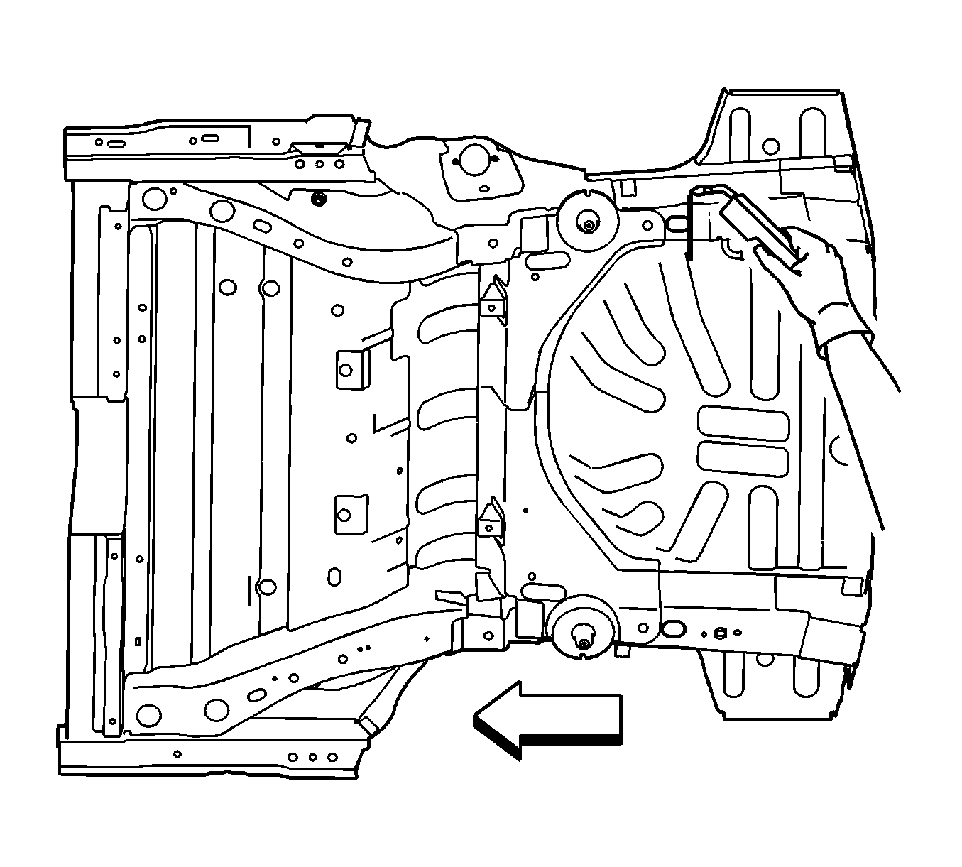
Important: The bumper mounting holes must be properly located and drilled. Use three-dimensional measuring equipment.
Important: Prior to refinishing, refer to publication GM 4901MD-01 GM Approved Refinish Materials for recommended products. Do not combine the paint systems. Refer to the paint manufacturer's recommendations.
| • | Sealers |
| • | Sound deadening materials |
| • | An approved anti-corrosion primer. |
