Catalytic Converter Replacement LX9 - Front
Tools Required
J 39194-B Heated Oxygen Sensor Wrench
Removal Procedure
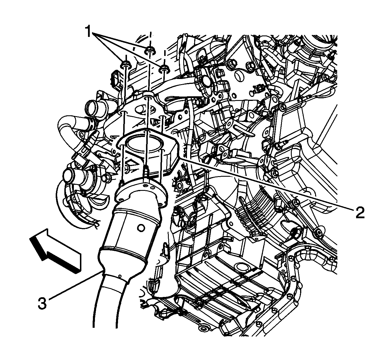
- Remove the front catalytic converter nuts (1) at the exhaust manifold.
- Remove the muffler assembly. Refer to Muffler Replacement .
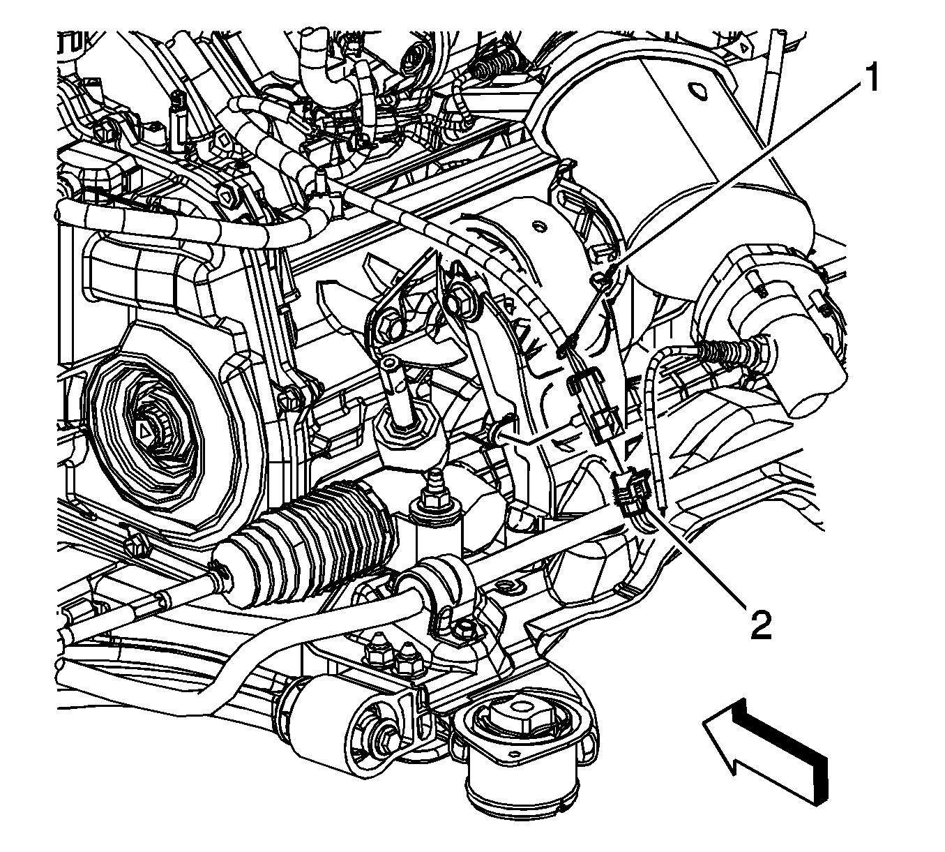
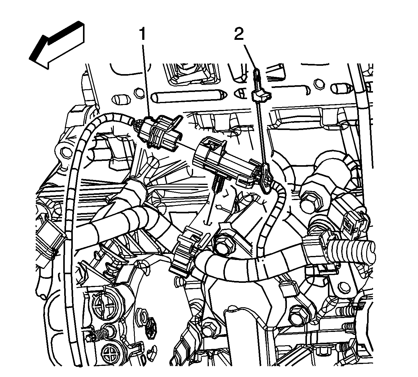
- Remove the rear heated oxygen sensor (HO2S) connector position assurance (CPA) retainer (1).
- Disconnect the rear HO2S electrical connector (2).
- Remove the front HO2S CPA retainer (2).
- Disconnect the front HO2S electrical connector (1).
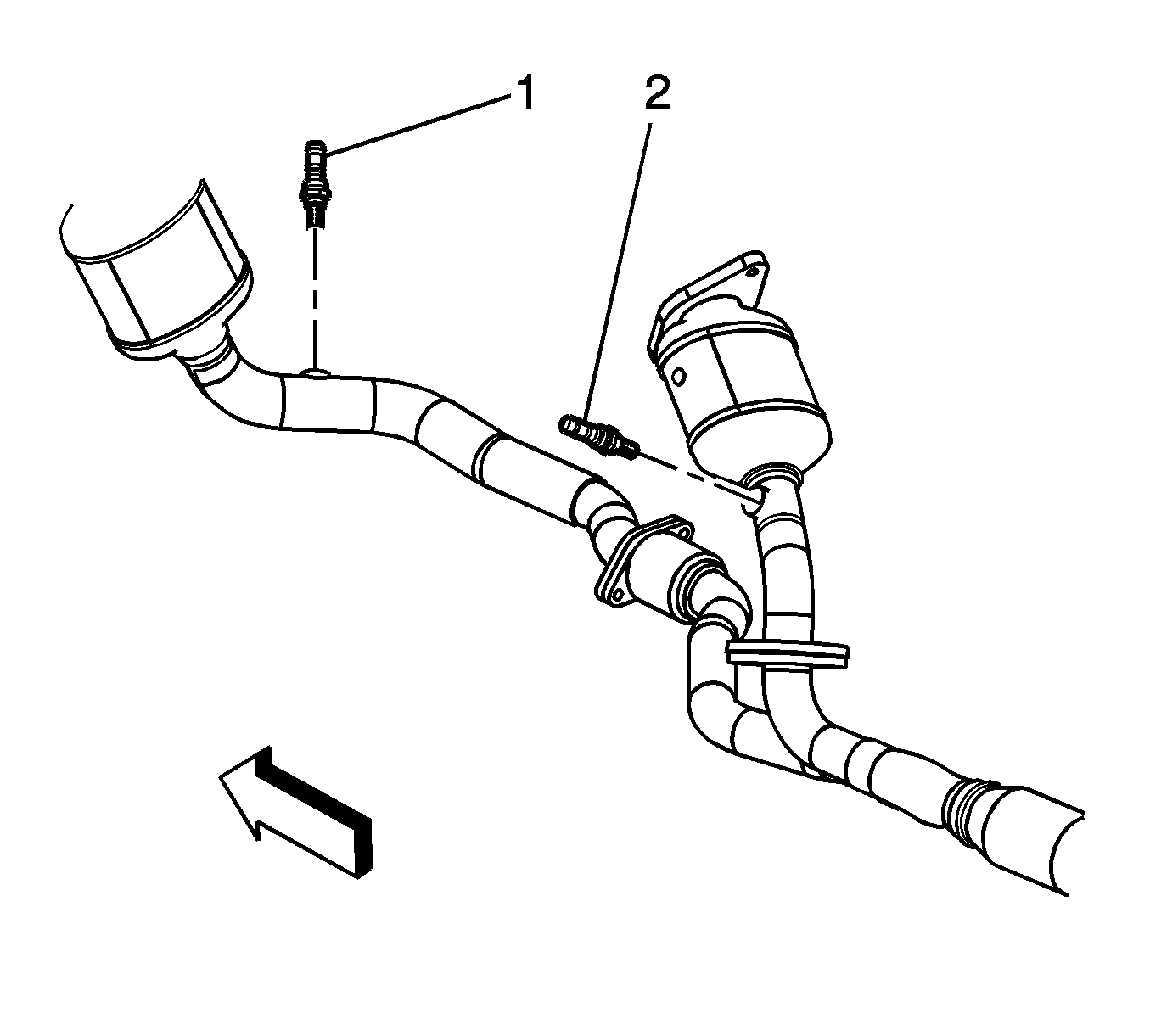
- Remove the front and rear HO2Ss (1, 2) using the J 39194-B .
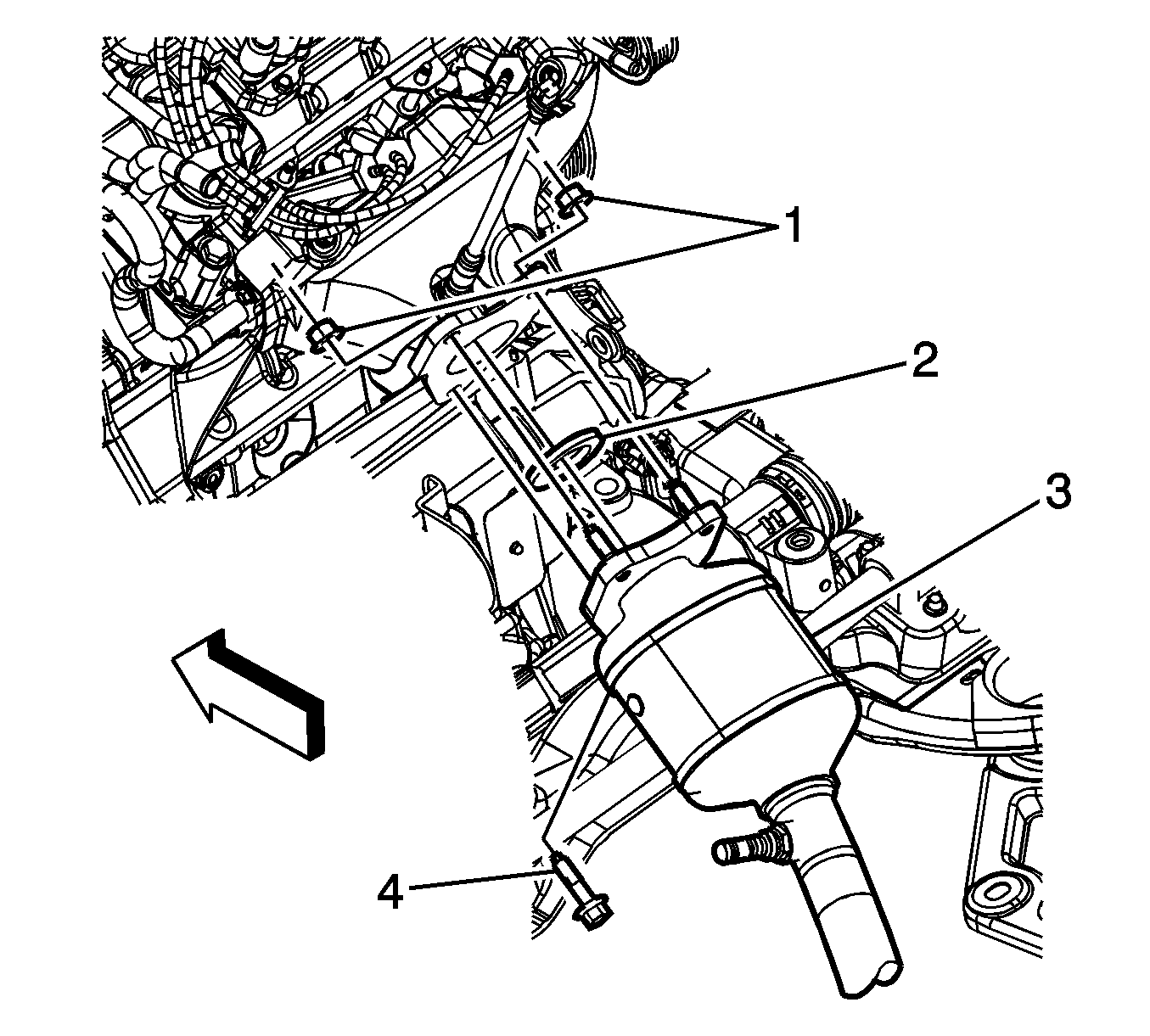
- Remove the rear catalytic converter bolt (4) and nuts (1) at the exhaust manifold.
- Remove and discard the gasket (2).
- Remove the rear catalytic converter (3).
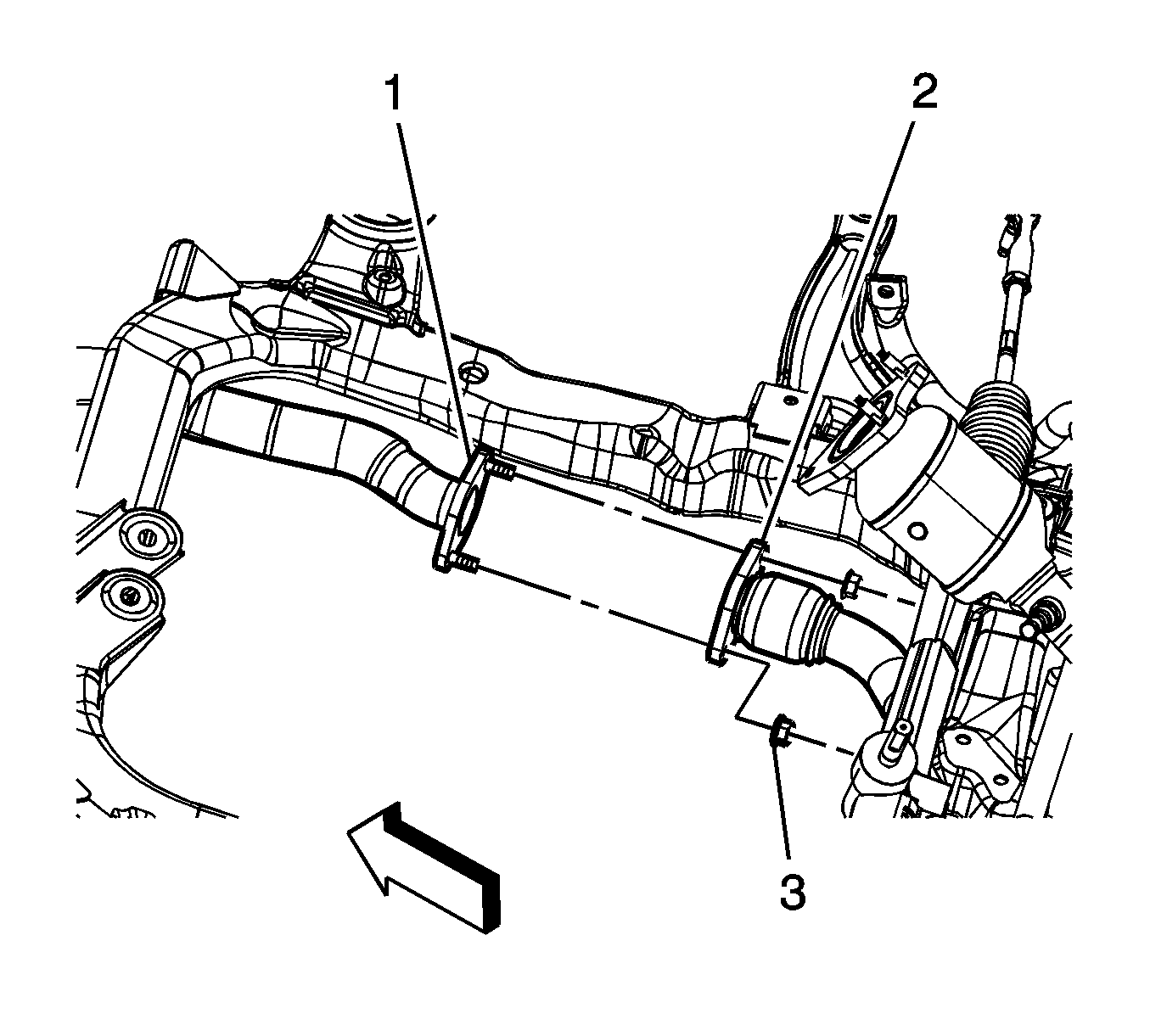
- Remove the front catalytic converter to rear catalytic converter nuts (3). (Powertrain shown removed for clarity).
- Remove the front catalytic converter (1)
- Remove and discard the front catalytic converter to manifold gasket.
- Inspect the catalytic converter-to-exhaust manifold flange.
Important: The HO2S uses a permanently attached pigtail and connector. This pigtail should not be removed from the sensor. Damage or removal of the pigtail or connector will affect proper operation of the sensor.
Important: The HO2S uses a permanently attached pigtail and connector. This pigtail should not be removed from the sensor. Damage or removal of the pigtail or connector will affect proper operation of the sensor.
Catalytic Converter to Manifold Flange Warpage:
| • | Service Limit: 0.7 mm (0.028 in) max. |
| • | Standard: 0.7 mm (0.028 in) max. |
Installation Procedure
- Install a NEW gasket to the front catalytic converter studs.
- Install the front catalytic converter (1)
- Install a NEW gasket (2) to the rear catalytic converter studs.
- Install the rear catalytic converter (3).
- Install the rear catalytic converter bolt (4) and nuts (1) at the exhaust manifold.
- Install the front catalytic converter to rear catalytic converter nuts (3). (Powertrain shown removed for clarity).
- Install the front and rear HO2Ss (1, 2) using the J 39194-B .
- Connect the front HO2S electrical connector (1).
- Install the front HO2S CPA retainer (2).
- Disconnect the rear HO2S electrical connector (2).
- Install the rear HO2S CPA retainer (1).
- Install the muffler assembly. Refer to Muffler Replacement .
- Install the front catalytic converter nuts (1) at the exhaust manifold.
- Start the engine, and check for exhaust leaks.

Notice: Refer to Fastener Notice in the Preface section.
Tighten
Tighten the bolt and nuts to 31 N·m (23 lb ft).

Tighten
Tighten the nuts to 31 N·m (23 lb ft).

Tighten
Tighten the sensor to 42 N·m (31 lb ft).


Tighten
Tighten the nuts to 31 N·m (23 lb ft).
Catalytic Converter Replacement LX9 - Rear
Tools Required
J 39194-B Heated Oxygen Sensor Wrench
Removal Procedure
- Remove the muffler assembly. Refer to Muffler Replacement .
- Remove the connector position assurance (CPA) retainer (1).
- Disconnect the HO2S electrical connector (2).
- Remove the HO2S (2) using the J 39194-B .
- Remove the front catalytic converter to rear catalytic converter nuts (3). (Powertrain shown removed for clarity).
- Remove the catalytic converter bolt (4) and nuts (1) at the exhaust manifold.
- Remove the rear catalytic converter 3).
- Remove and discard the gasket (2).
- Inspect the catalytic converter-to-exhaust manifold flange.

Important: The heated oxygen sensor (HO2S) 2 uses a permanently attached pigtail and connector. This pigtail should not be removed from the sensor. Damage or removal of the pigtail or connector will affect proper operation of the sensor.


Catalytic Converter to Manifold Flange Warpage:
| • | Service Limit: 0.7 mm (0.028 in) max. |
| • | Standard: 0.7 mm (0.028 in) max. |
Installation Procedure
- Install a NEW gasket (2) to the catalytic converter studs.
- Install the rear catalytic converter (3).
- Install the catalytic converter bolt (4) and nuts (1) at the exhaust manifold.
- Install the front catalytic converter to rear catalytic converter nuts (3). (Powertrain shown removed for clarity).
- Install the HO2S (2) using the J 39194-B .
- Connect the HO2S electrical connector (2).
- Install the CPA retainer (1).
- Install the muffler assembly. Refer to Muffler Replacement .
- Start the engine, and check for exhaust leaks.

Notice: Refer to Fastener Notice in the Preface section.
Tighten
Tighten the bolt and nuts to 31 N·m (23 lb ft).

Tighten
Tighten the nuts to 31 N·m (23 lb ft).

Tighten
Tighten the sensor to 42 N·m (31 lb ft).

Catalytic Converter Replacement 3.9L Engine - Front
Tools Required
J 39194-B Heated Oxygen Sensor Wrench
Removal Procedure
- Remove the air cleaner assembly. Refer to Air Cleaner Assembly Replacement .
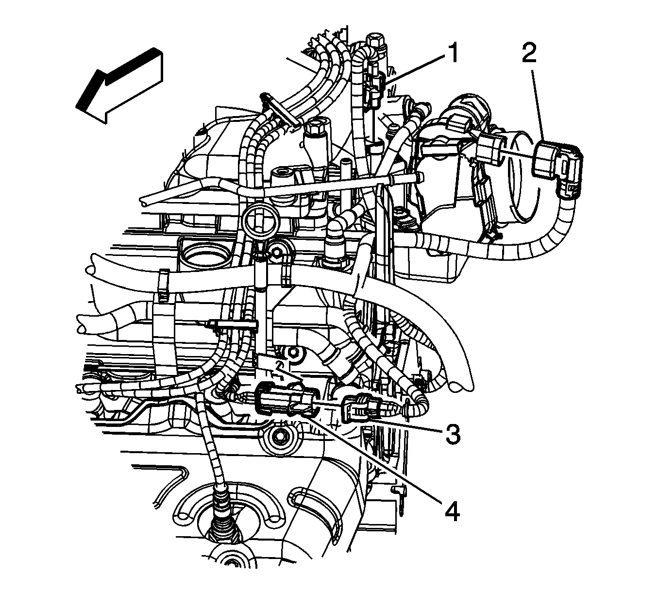
- Remove the connector position assurance (CPA) retainer (5).
- Disconnect the heated oxygen sensor (HO2S) electrical connector (4).
- Remove the HO2S clip (3) from the oil level indicator tube bracket.
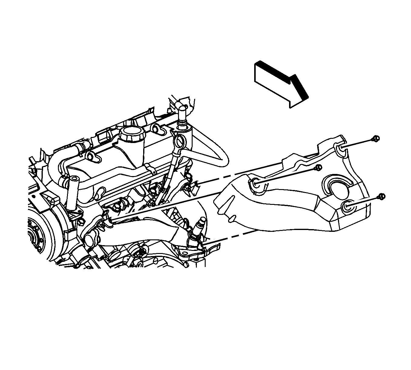
- Remove the exhaust manifold heat shield bolts.
- Remove the exhaust manifold heat shield.
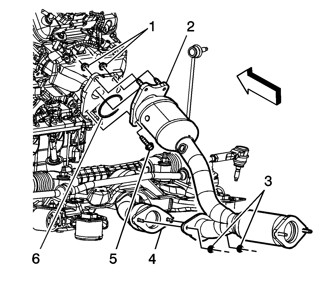
- Remove the left (front) catalytic converter nuts (1) at the exhaust manifold.
- Remove the muffler assembly. Refer to Muffler Replacement .
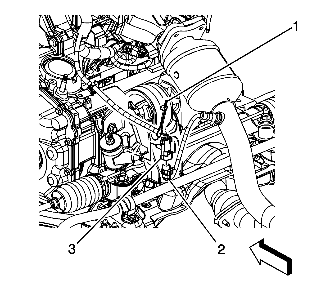
- Remove the lower right heated oxygen sensor HO2S connector position assurance (CPA) retainer (1).
- Disconnect the rear HO2S electrical connector (2).
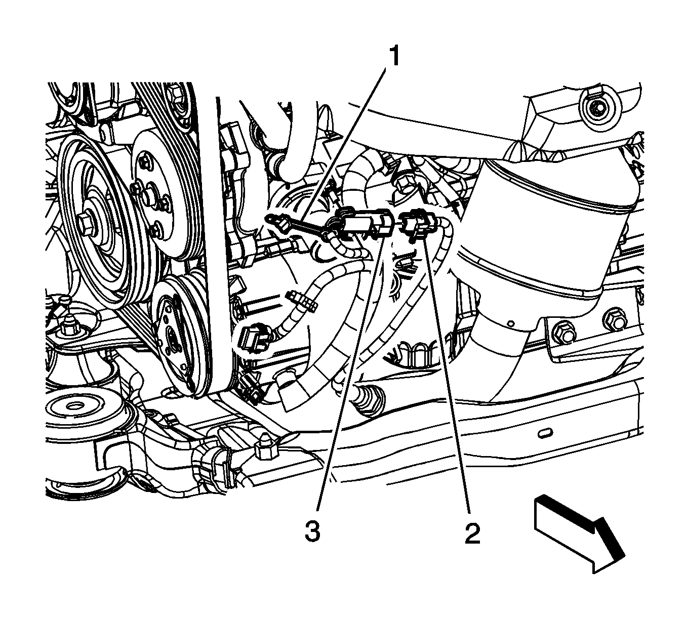
- Remove the lower left HO2S CPA retainer (1).
- Disconnect the front HO2S electrical connector (2).
- Remove the lower right and left HO2S (1, 2) using the J 39194-B .
- Remove the left (front) catalytic converter to right (rear) catalytic converter nuts (3).
- Remove the right (rear) catalytic converter bolt (5) and nuts (1) at the exhaust manifold.
- Remove and discard the gasket (6).
- Remove the right (rear) catalytic converter (2).
- Remove the left (front) catalytic converter (4).
- Remove and discard the left (front) catalytic converter to manifold gasket.
- Inspect the catalytic converter-to-exhaust manifold flange.


Notice: The oxygen sensor uses a permanently attached pigtail and connector. Do not remove the pigtail from the oxygen sensor. Damage to or removal of the pigtail connector could affect proper operation of the oxygen sensor.
Catalytic Converter to Manifold Flange Warpage
| • | Service Limit: 0.7 mm (0.028 in) max. |
| • | Standard: 0.7 mm (0.028 in) max. |
Installation Procedure
- Install a NEW gasket to the left (front) catalytic converter studs.
- Install the left (front) catalytic converter (4).
- Install a NEW gasket (6) to the right (rear) catalytic converter studs.
- Install the right (rear) catalytic converter (2).
- Install the right (rear) catalytic converter bolt (5) and nuts (1) at the exhaust manifold.
- Install the left (front) catalytic converter to right (rear) catalytic converter nuts (3).
- If reinstalling the old HO2S, coat the threads with anti-seize compound GM P/N 12377953 or equivalent.
- Install the lower right and left HO2S (1, 2) using the J 39194-B .
- Connect the lower left HO2S electrical connector (1).
- Install the lower left HO2S CPA retainer (2).
- Connect the lower right HO2S electrical connector (2).
- Install the lower right HO2S CPA retainer (1).
- Install the muffler assembly. Refer to Muffler Replacement .
- Install the left (front) catalytic converter nuts (1) at the exhaust manifold.
- Install the exhaust manifold heat shield.
- Install the exhaust manifold heat shield bolts.
- Connect the HO2S electrical connector (4).
- Install the CPA retainer (5).
- Install the HO2S clip (3) to the oil level indicator tube bracket.
- Install the air cleaner assembly. Refer to Air Cleaner Assembly Replacement .
- Perform the engine mount position adjustment procedure. Refer to Engine Mount Position Adjustment .
- Start the engine, and check for exhaust leaks.

Notice: Refer to Fastener Notice in the Preface section.
Tighten
Tighten the bolt and nuts to 31 N·m (23 lb ft).
Tighten
Tighten the nuts to 31 N·m (23 lb ft).

Important: A special anti-seize compound is used on the HO2S threads. The compound consists of liquid graphite and glass beads. The graphite tends to burn away but the beads remain, making the sensor easier the remove. New, or service replacement sensors already have the compound applied to the threads. If the sensor is removed from an exhaust component and if for any reason the sensor is to be reinstalled, the threads must be have anti-seize compound applied before the reinstallation.
Tighten
Tighten the sensor to 42 N·m (31 lb ft).


Tighten
Tighten the nuts to 31 N·m (23 lb ft).

Tighten
Tighten the bolts to 10 N·m (89 lb in).

Catalytic Converter Replacement 3.9L Engine - Rear
Tools Required
J 39194-B Heated Oxygen Sensor Wrench
Removal Procedure
- Remove the muffler assembly. Refer to Muffler Replacement .
- Remove the rear stabilizer shaft. Refer to Stabilizer Shaft Replacement .
- Remove the connector position assurance (CPA) retainer (1).
- Disconnect the lower right heated oxygen sensor (HO2S) electrical connector (2).
- Remove the lower right HO2S (2) using the J 39194-B .
- Remove the left (front) catalytic converter to right (rear) catalytic converter nuts (3).
- Remove the right (rear) catalytic converter bolt (5) and nuts (1) at the exhaust manifold.
- Remove the right catalytic converter (2).
- Remove and discard the gasket (6).
- Inspect the catalytic converter-to-exhaust manifold flange.


Notice: The oxygen sensor uses a permanently attached pigtail and connector. Do not remove the pigtail from the oxygen sensor. Damage to or removal of the pigtail connector could affect proper operation of the oxygen sensor.

Catalytic Converter to Manifold Flange Warpage:
| • | Service Limit: 0.7 mm (0.028 in) max. |
| • | Standard: 0.7 mm (0.028 in) max. |
Installation Procedure
- Install a NEW gasket to the catalytic converter.
- Install the right (rear) catalytic converter (2).
- Install the right (rear) catalytic converter bolt (4) and nuts (1) at the exhaust manifold.
- Install the left (front) catalytic converter to right (rear) catalytic converter nuts (3).
- If reinstalling the old HO2S, coat the threads with anti-seize compound GM P/N 12377953 or equivalent.
- Install the HO2S (2) using the J 39194-B .
- Connect the lower right HO2S electrical connector (2).
- Install the CPA retainer (1).
- Ensure that the HO2S connector clip (3) is attached to the stud on the engine.
- Install the rear stabilizer shaft. Refer to Stabilizer Shaft Replacement .
- Install the muffler assembly. Refer to Muffler Replacement .
- Perform the engine mount position adjustment procedure. Refer to Engine Mount Position Adjustment .
- Start the engine, and check for exhaust leaks.

Notice: Refer to Fastener Notice in the Preface section.
Tighten
Tighten the nuts to 31 N·m (23 lb ft).
Tighten
Tighten the nuts to 31 N·m (23 lb ft).

Important: A special anti-seize compound is used on the HO2S threads. The compound consists of liquid graphite and glass beads. The graphite tends to burn away but the beads remain, making the sensor easier the remove. New, or service replacement sensors already have the compound applied to the threads. If the sensor is removed from an exhaust component and if for any reason the sensor is to be reinstalled, the threads must be have anti-seize compound applied before the reinstallation.
Tighten
Tighten the sensor to 42 N·m (31 lb ft).

