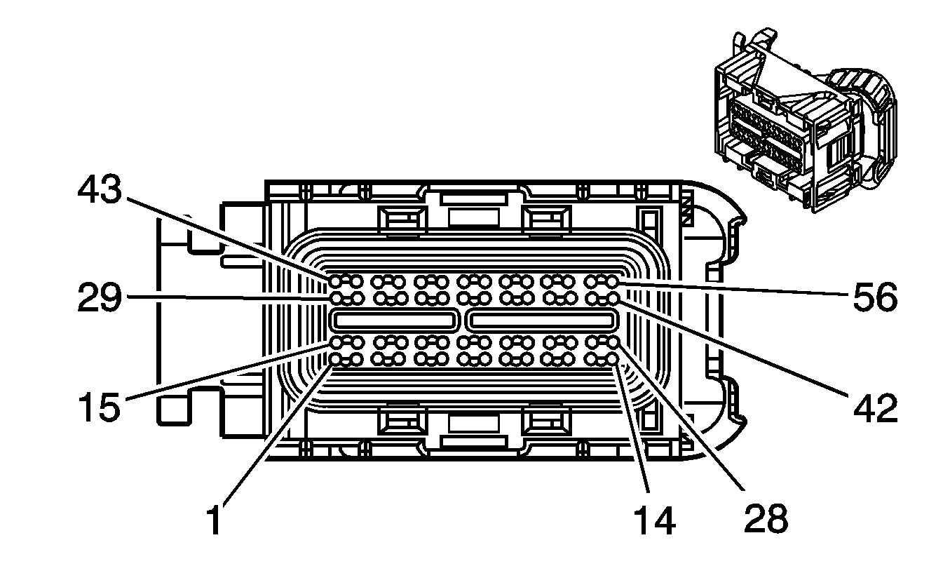
| Connector 1: | Powertrain Control Module (PCM) C1 |
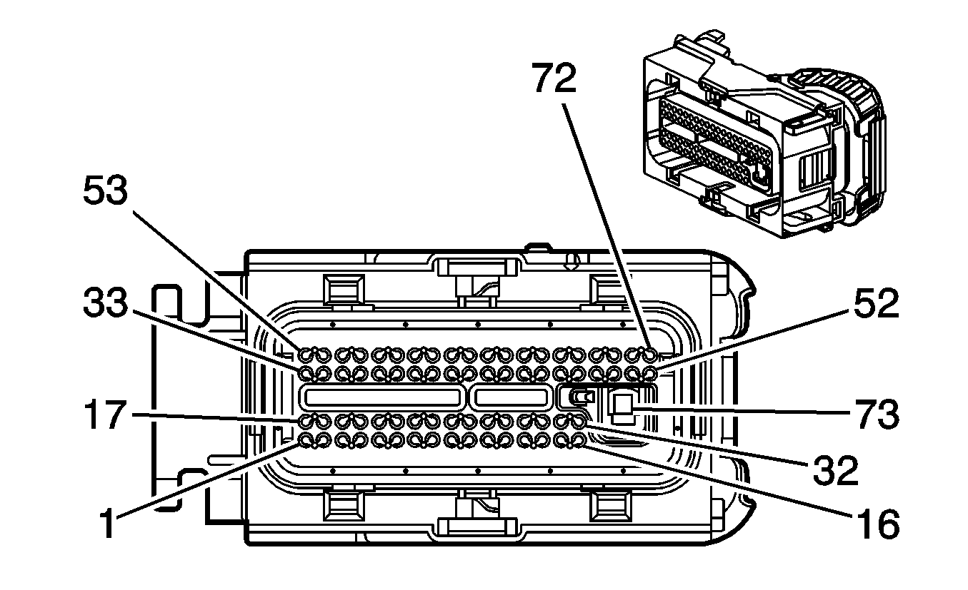
| Connector 2: | Powertrain Control Module (PCM) C2 |
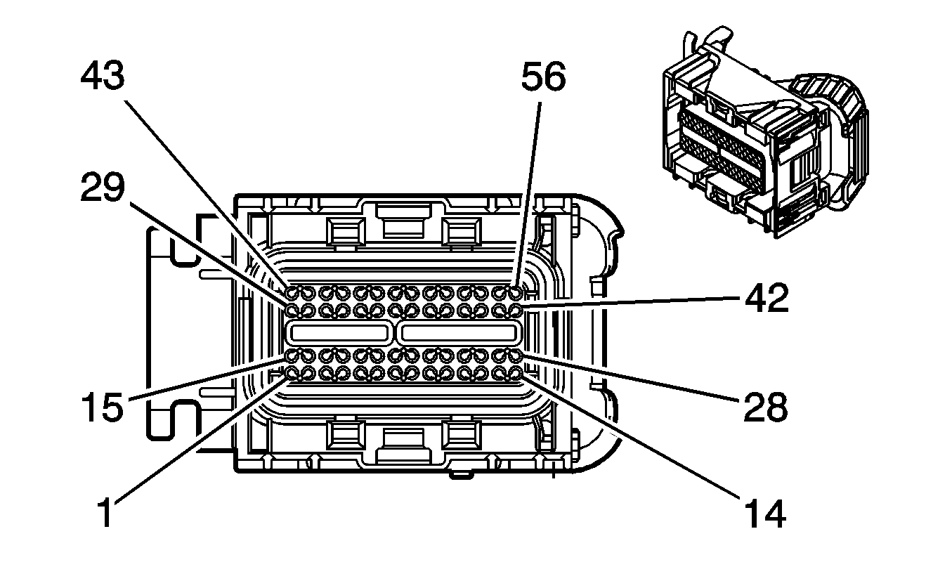
| Connector 3: | Powertrain Control Module (PCM) C3 |
Powertrain Control Module (PCM) C1

Connector Part Information
|
Terminal Part Information
|
Pin | Wire Color | Circuit No. | Function |
|---|---|---|---|
1 | TN/BK | 2500 | High Speed GMLAN Serial Data Bus+ |
2 | TN | 2501 | High Speed GMLAN Serial Data Bus- |
3 | -- | -- | Not Used |
4 | GY | 2700 | 5-Volt Reference 2 |
5 | -- | -- | Not Used |
6 | BN/WH | 419 | MIL Control |
7 | TN | 5514 | Low Reference |
8 | OG/BK | 1057 | Low Reference |
9 | -- | -- | Not Used |
10 | WH | 1310 | EVAP Canister Vent Solenoid Control |
11 | -- | -- | Not Used |
12 | OG/BK | 1057 | Low Reference |
13-14 | -- | -- | Not Used |
15 | PU | 1807 | Class 2 Serial Data (Primary) |
16-17 | -- | -- | Not Used |
18 | BN | 4 | Accessory Voltage |
19 | PK | 639 | Ignition 1 Voltage |
20 | RD/WH | 540 | Battery Positive Voltage |
21 | -- | -- | Not Used |
22 | BN | 818 | Vehicle Speed Signal |
23 | YE | 447 | Starter Relay Coil Control |
24 | BN | 5069 | Main Relay Control |
25 | -- | -- | Not Used |
26 | D-GN | 890 | Fuel Tank Pressure Sensor Signal |
27-30 | -- | -- | Not Used |
31 | OG/BK | 380 | A/C Refrigerant Pressure Sensor Signal |
32 | WH | 17 | Stop Lamp Switch Signal |
33 | D-GN/WH | 459 | A/C Compressor Clutch Relay Control |
34-36 | -- | -- | Not Used |
37 | D-GN/WH | 465 | Fuel Pump Relay Control High |
38-42 | -- | -- | Not Used |
43 | PU | 1589 | Fuel Level Sensor Signal |
44 | -- | -- | Not Used |
45 | PU | 5526 | Tap Up/Tap Down Switch Signal |
46-47 | -- | -- | Not Used |
48 | D-GN | 335 | Low Speed Cooling Fan Relay Control |
49 | -- | -- | Not Used |
50 | D-BU | 473 | High Speed Cooling Fan Relay Control |
51-52 | -- | -- | Not Used |
53 | GY | 705 | 5-Volt Reference 1 |
54-56 | -- | -- | Not Used |
Powertrain Control Module (PCM) C2

Connector Part Information
|
Terminal Part Information
|
Pin | Wire Color | Circuit No. | Function |
|---|---|---|---|
1 | BN | 1456 | EGR Valve Position Signal |
2 | OG/BK | 1061 | UART Serial Data (Secondary) |
3 | TN | 800 | UART Serial Data (Primary) |
4 | PK/BK | 1746 | Fuel Injector 3 Control |
5 | TN | 1744 | Fuel Injector 1 Control |
6 | L-GN/BK | 1745 | Fuel Injector 2 Control |
7 | TN/WH | 845 | Fuel Injector 5 Control |
8 | TN | 2753 | Low Reference |
9 | YE/BK | 846 | Fuel Injector 6 Control |
10 | L-BU/BK | 844 | Fuel Injector 4 Control |
11 | OG/WH | 2122 | IC 2 Control |
12 | GY/WH | 3113 | HO2S Heater Low Control (Bank 1 Sensor 1) |
13 | OG | 1676 | EGR Solenoid High Control |
14 | -- | -- | Not Used |
15 | PU | 574 | Low Reference |
16 | GY | 435 | EGR Solenoid Low Control |
17 | -- | -- | Not Used |
18 | L-GN | 432 | MAP Sensor Signal |
19-20 | -- | -- | Not Used |
21 | OG | 631 | 12-Volt Reference |
22 | L-GN | 1867 | 12-Volt Reference |
23-24 | -- | -- | Not Used |
25 | TN/WH | 3211 | HO2S Low Reference (Bank 2 Sensor 1) |
26 | BN/WH | 633 | CMP Sensor Signal |
27 | L-BU/BK | 647 | Medium Resolution Engine Speed Signal |
28-29 | -- | -- | Not Used |
30 | OG/BK | 469 | Low Reference |
31 | -- | -- | Not Used |
32 | PK/BK | 632 | Low Reference |
33 | GY | 5047 | 5-Volt Reference |
34 | GY | 2704 | 5-Volt Reference 1 |
35 | -- | -- | Not Used |
36 | GY | 2303 | Low Reference |
37 | YE | 2174 | Low Reference |
38 | D-BU | 496 | Knock Sensor 1 Signal |
39 | GY/BK | 1798 | Drain Wire |
40 | GY | 1716 | Low Reference |
41 | D-GN/WH | 428 | EVAP Canister Purge Solenoid Control |
42-46 | -- | -- | Not Used |
47 | TN/WH | 3111 | HO2S Low Reference (Bank 1 Sensor 1) |
48 | PU/WH | 3110 | HO2S Reference Voltage (Bank 1 Sensor 1) |
49-52 | -- | -- | Not Used |
53 | OG | 225 | Generator Turn On Signal |
54 | L-BU | 1876 | Knock Sensor 2 Signal |
55 | YE | 410 | ECT Sensor Signal |
56 | OG/BK | 645 | Drain Wire |
57 | TN/BK | 231 | Oil Pressure Switch Signal |
58-59 | -- | -- | Not Used |
60 | PU/WH | 3210 | HO2S Reference Voltage (Bank 2 Sensor 1) |
61 | PU | 2121 | IC 1 Control |
62 | L-GN | 3212 | HO2S Heater Low Control (Bank 2 Sensor 1) |
63 | L-BU | 2123 | IC 3 Control |
64-72 | -- | -- | Not Used |
73 | BK/WH | 451 | Ground |
Powertrain Control Module (PCM) C3

Connector Part Information
|
Terminal Part Information
|
Pin | Wire Color | Circuit No. | Function |
|---|---|---|---|
1-2 | -- | -- | Not Used |
3 | TN | 3221 | HO2S Low Signal (Bank 2 Sensor 2) |
4 | TN/WH | 3121 | HO2S Low Signal (Bank 1 Sensor 2) |
5 | YE/BK | 1227 | TFT Sensor Signal |
6 | YE | 492 | MAF Sensor Signal |
7 | -- | -- | Not Used |
8 | GY/WH | 3122 | HO2S Heater Low Control (Bank 1 Sensor 2) |
9 | -- | -- | Not Used |
10 | OG/WH | 3223 | HO2S Heater Low Control (Bank 2 Sensor 2) |
11 | OG/BK | 1230 | A/T ISS High Signal |
12 | YE | 400 | VSS High Signal |
13-14 | -- | -- | Not Used |
15 | GY | 773 | Transmission Range Switch Signal C |
16-17 | -- | -- | Not Used |
18 | PU | 3220 | HO2S High Signal (Bank 2 Sensor 2) |
19 | PU | 3120 | HO2S High Signal (Bank 1 Sensor 2) |
20-21 | -- | -- | Not Used |
22 | YE | 772 | Transmission Range Switch Signal B |
23 | WH | 776 | Transmission Range Switch Signal P |
24 | YE | 657 | TCC Release Switch Signal |
25 | -- | -- | Not Used |
26 | TN | 472 | IAT Sensor Signal |
27-28 | -- | -- | Not Used |
29 | D-BU | 1225 | Transmission Fluid Pressure Switch Signal B |
30 | OG | 1226 | Transmission Fluid Pressure Switch Signal C |
31-32 | -- | -- | Not Used |
33 | L-GN | 1222 | 1-2 Shift Solenoid Valve Control |
34 | TN/WH | 771 | Transmission Range Switch Signal A |
35-38 | -- | -- | Not Used |
39 | BN | 418 | TCC PWM Solenoid Valve Control |
40-43 | -- | -- | Not Used |
44 | PU | 401 | VSS Low Signal |
45 | -- | -- | Not Used |
46 | YE/BK | 1223 | 2-3 Shift Solenoid Valve Control |
47 | OG/BK | 1228 | PC Solenoid Valve High Control (Sol. A) |
48 | TN | 2762 | Low Reference |
49 | D-BU/WH | 1231 | A/T ISS Low Signal |
50 | TN/BK | 2760 | Low Reference |
51 | L-BU/WH | 1229 | PC Solenoid Valve Low Control (Sol. A) |
52-56 | -- | -- | Not Used |
