For 1990-2009 cars only
Removal Procedure
- Raise and support the vehicle. Refer to Lifting and Jacking the Vehicle .
- Remove the front tires and wheels. Refer to Tire and Wheel Removal and Installation .
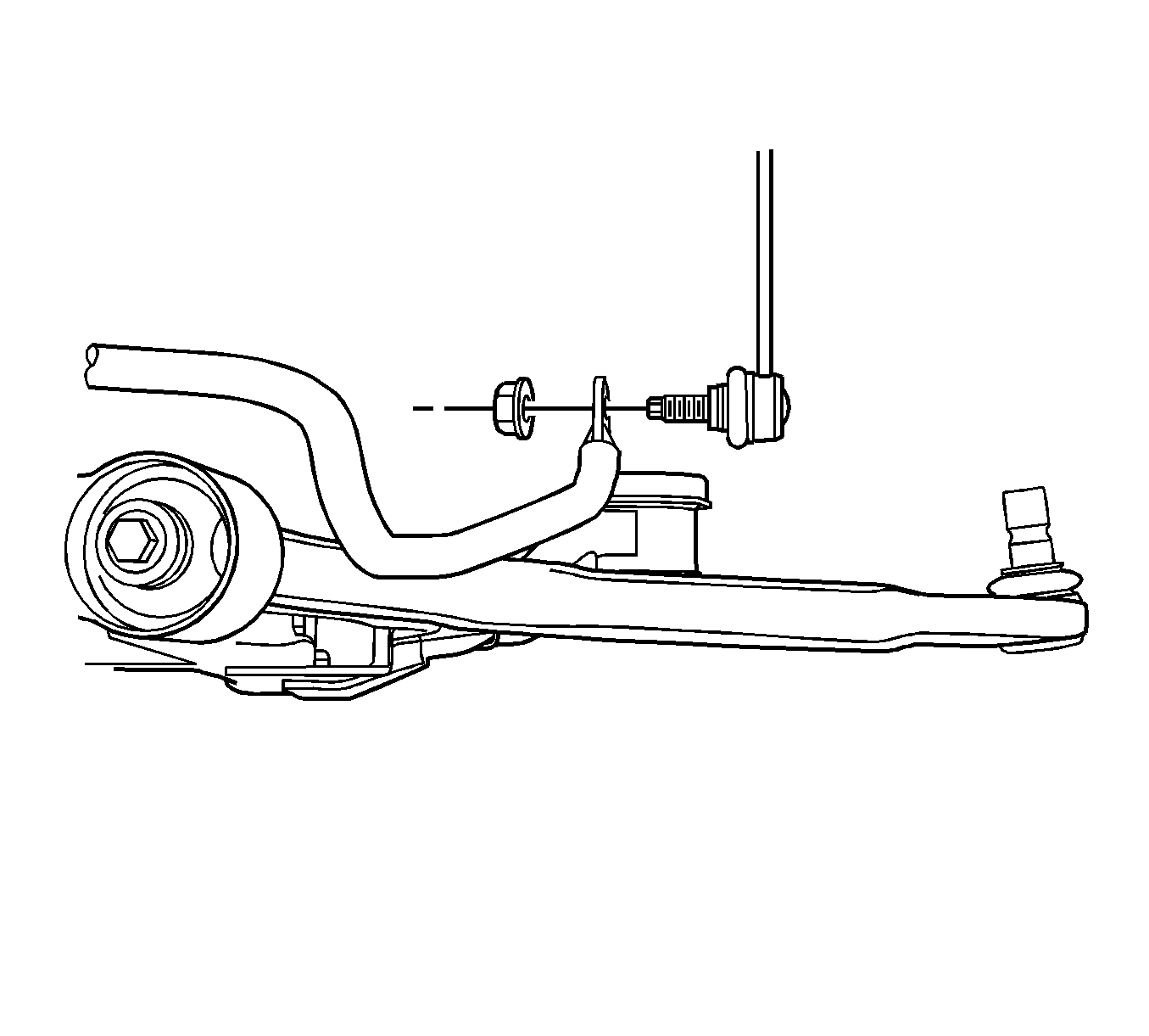
- Disconnect the stabilizer links from the stabilizer shaft. Refer to Stabilizer Shaft Link Replacement .
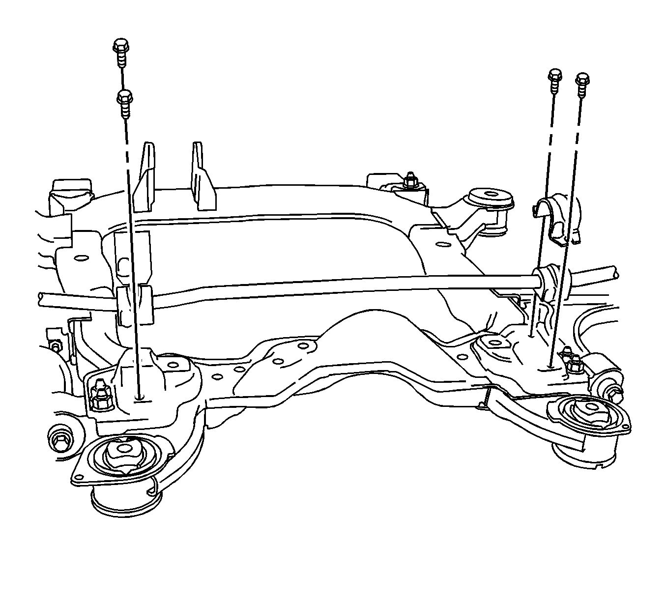
- Using a suitable jack stand, support the rear of the frame assembly.
- Remove the frame support to body bolts.
- Remove the rear frame assembly mounting bolts.
- Lower the rear of the cradle in order to gain clearance to the stabilizer shaft.
- Remove the stabilizer bar clamps and insulators. Refer to Stabilizer Shaft Insulator Replacement .
- Remove the stabilizer shaft through the opening between the frame and body.


Installation Procedure
- Position the stabilizer shaft to the frame.
- Install the stabilizer bar clamps and insulators. Refer to Stabilizer Shaft Insulator Replacement .
- Raise the rear of the cradle.
- Install the frame support brackets. Loosely install the bracket and frame to body bolts.
- Tighten the frame and bracket support bolts.
- Tighten the rear frame to body bolt to 100 N·m (74 lb ft) plus an additional 90 degrees.
- Tighten the frame support bracket to body bolt to 100 N·m (74 lb ft).
- Remove the jack stand.
- Connect the stabilizer link to the stabilizer bar. Refer to Stabilizer Shaft Link Replacement .
- Lower the vehicle.

Notice: Refer to Fastener Notice in the Preface section.
Important: The frame bolts require a minimum of 110 N·m (81 lb ft).
Tighten

