For 1990-2009 cars only
Tools Required
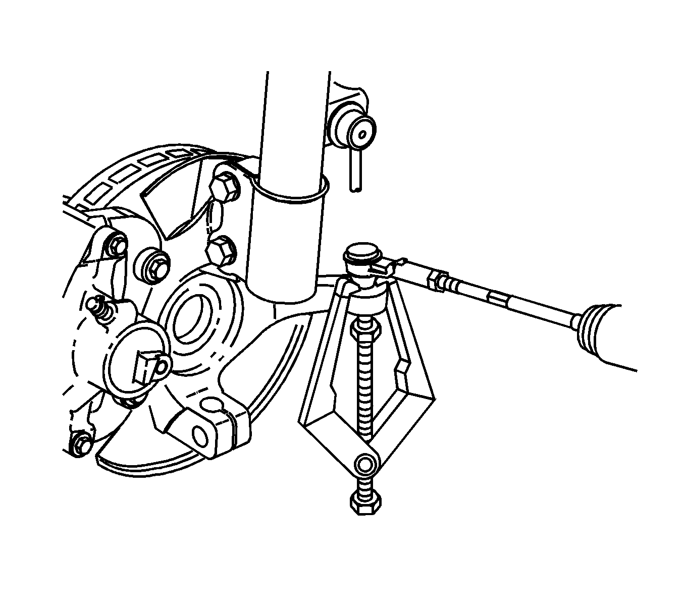
J 24319-B Universal Steering Linkage Puller
Removal Procedure
- Raise and support the vehicle. Refer to Lifting and Jacking the Vehicle .
- Remove the wheel bearing. Refer to Front Wheel Bearing and Hub Replacement .
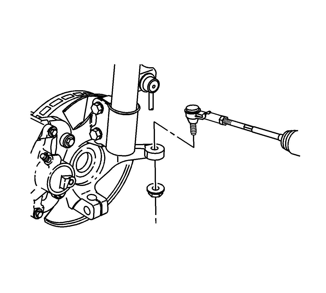
- Remove the outer tie rod to knuckle nut.
- Using the J 24319-B , separate the tie rod from the steering knuckle.
- Remove the lower control arm. Refer to Lower Control Arm Replacement .
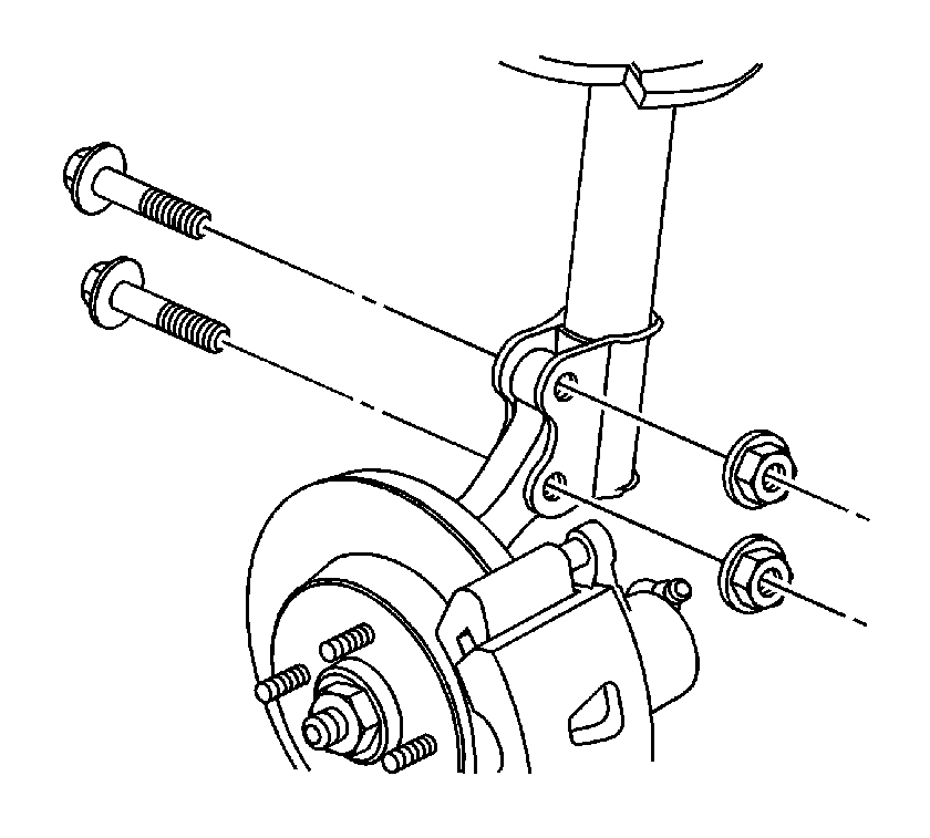
- Remove the strut to steering knuckle nuts and bolts.
- Remove the steering knuckle from the vehicle.


Installation Procedure
- Install the steering knuckle to the strut assembly and if applicable the ABS harness bracket.
- Guide the axle through the steering knuckle.
- Install the lower control arm. Refer to Lower Control Arm Replacement .
- Install the outer tie rod to the steering knuckle.
- Tighten the nut to 20 N·m (15 lb ft).
- Turn the nut an additional 180 degrees.
- Verify the torque to 50 N·m (37 lb ft).
- Install the wheel bearing, brake rotor, brake caliper and front wheels. Refer to Front Wheel Bearing and Hub Replacement .
- Lower the vehicle.
- Road test the vehicle in order to verify alignment. If a lead or pull is present refer to Wheel Alignment Measurement .
Notice: Refer to Fastener Notice in the Preface section.

Tighten
Tighten the bolts and nuts to 120 N·m (89 lb ft).

Tighten
