For 1990-2009 cars only
Removal Procedure
- Raise and support the vehicle. Refer to Lifting and Jacking the Vehicle .
- Remove the tire and wheel. Refer to Tire and Wheel Removal and Installation .
- If equipped with an antilock brake system (ABS) system, disconnect the ABS harness connector and route the harness aside. Note the routing for assembly.
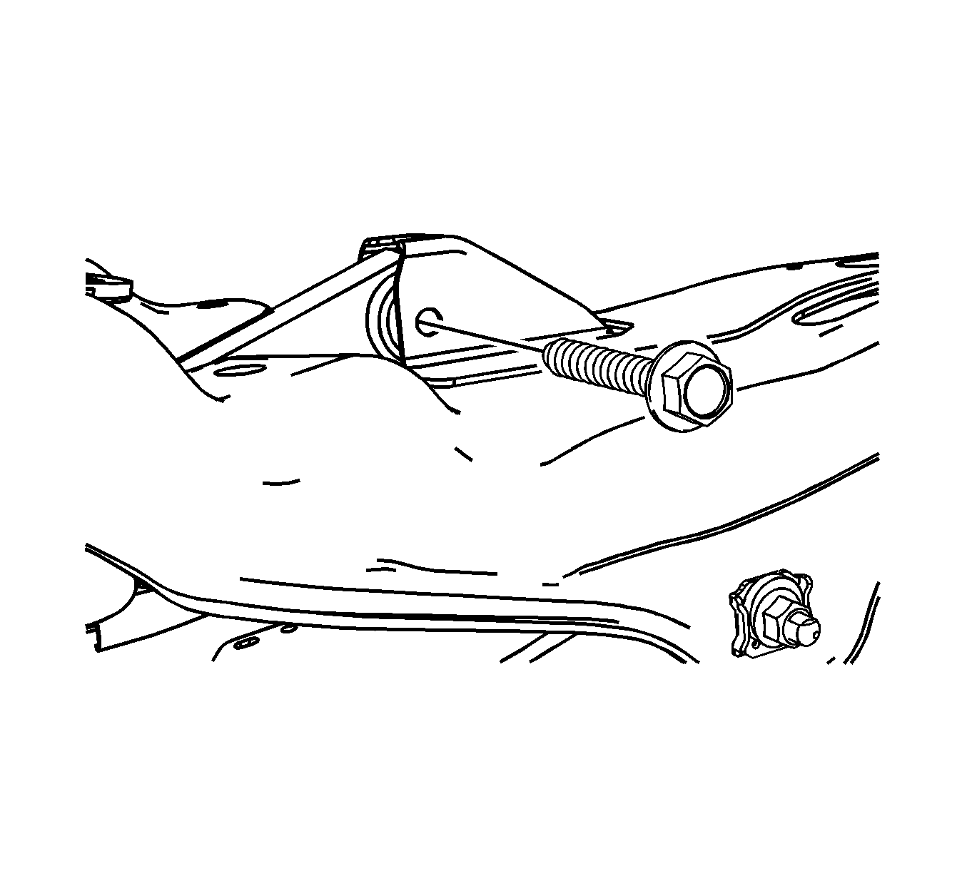
- Remove the upper control arm to support assembly bolt.
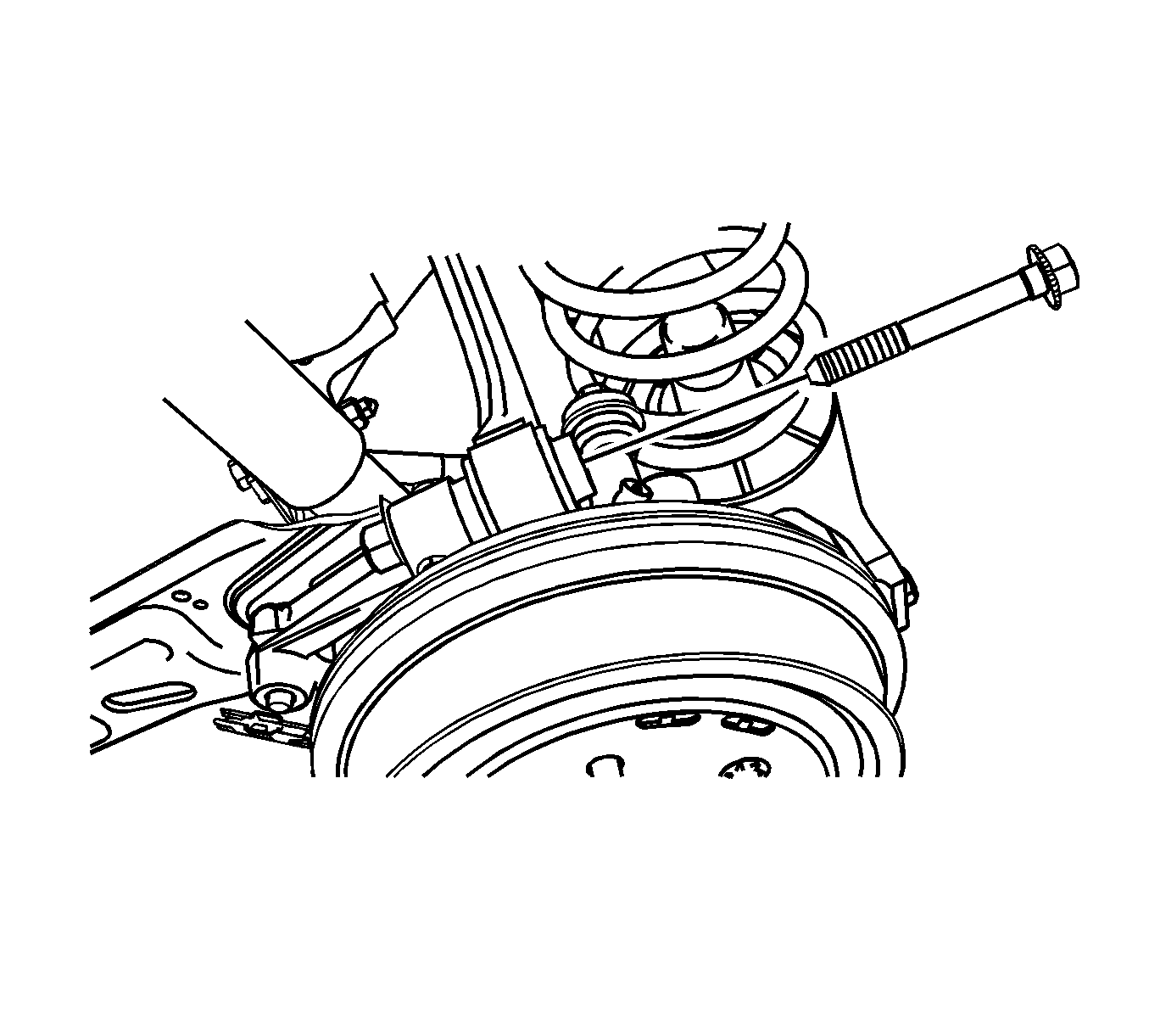
- Remove the upper control arm to knuckle bolt and nut.
- Remove the upper control arm from the vehicle through the wheel well opening.


Installation Procedure
- Position the upper control arm to the support assembly and knuckle.
- Install the upper control arm to knuckle bolt and nut. Hand tighten only.
- Install the upper control arm to support assembly bolt.
- If equipped with ABS, connect the ABS harness connector. Route the harness as previously noted.
- Install the tire and wheel. Refer to Tire and Wheel Removal and Installation .
- Lower the vehicle.

Notice: Refer to Fastener Notice in the Preface section.

Tighten
| • | Tighten the upper control arm to support assembly bolt to 60 N·m (44 lb ft) plus 60 degrees. |
| • | Tighten the upper control arm to knuckle bolt to 110 N·m (81 lb ft) plus 70 degrees. |
