For 1990-2009 cars only
Tools Required
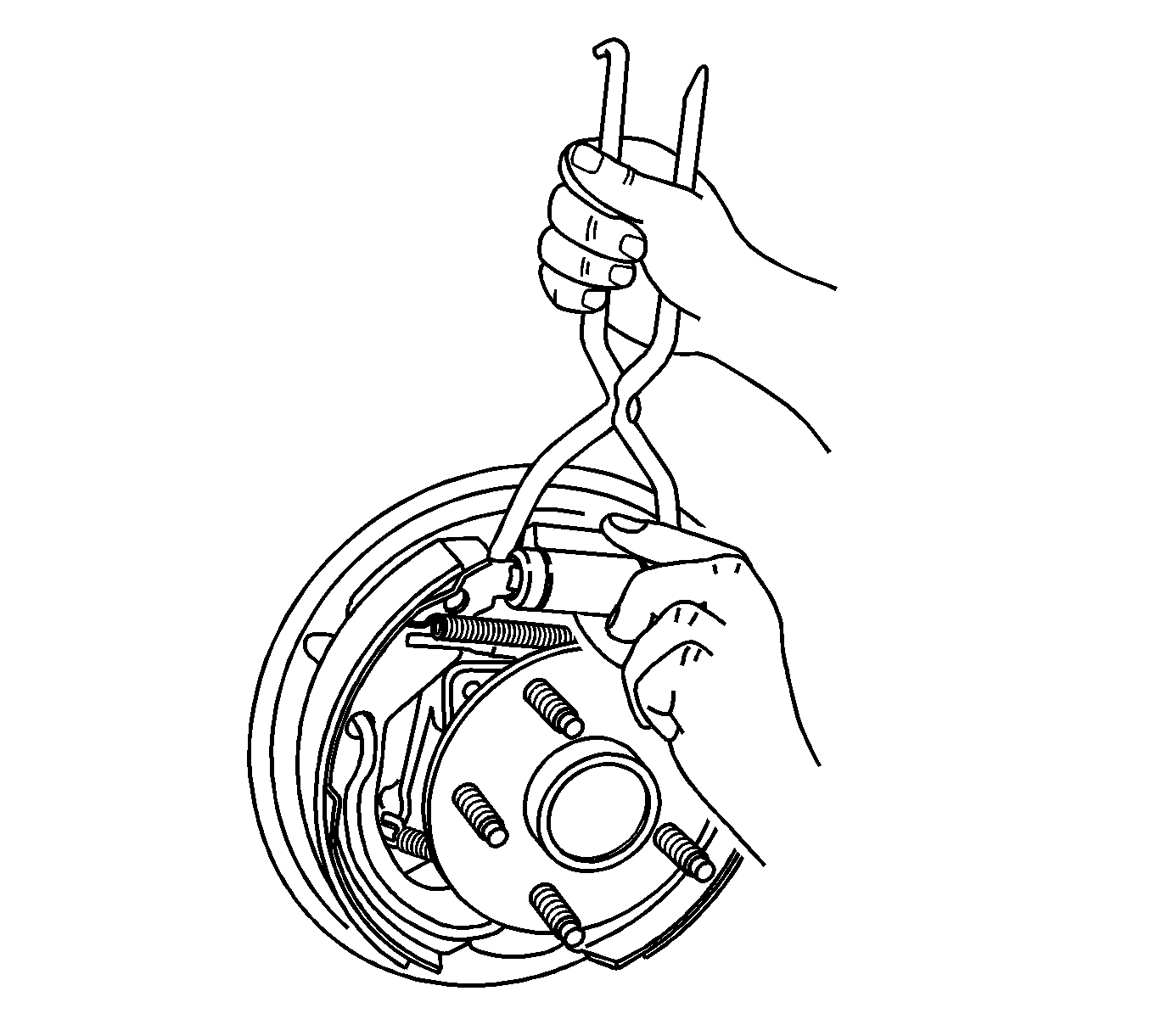
J 38400 Brake Shoe Spanner and Spring Remover
Removal Procedure
- Raise and support the vehicle. Refer to Lifting and Jacking the Vehicle.
- Remove the tire and wheel assembly. Refer to Tire and Wheel Removal and Installation.
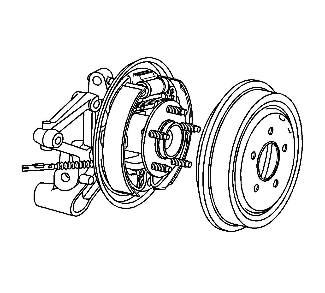
- Remove the brake drum. Refer to Brake Drum Replacement.
- Clean any debris and contaminants from around the brake hose banjo bolt to wheel cylinder connection.
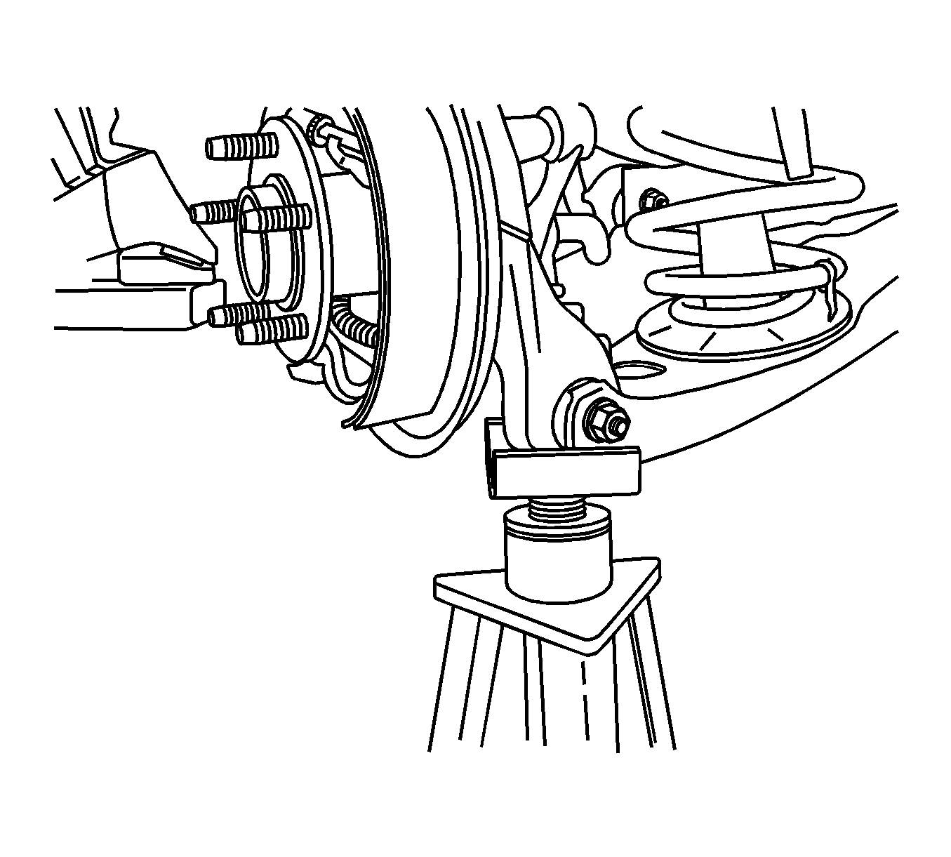
- Support the lower control arm assembly with a jack stand or suitable support fixture.
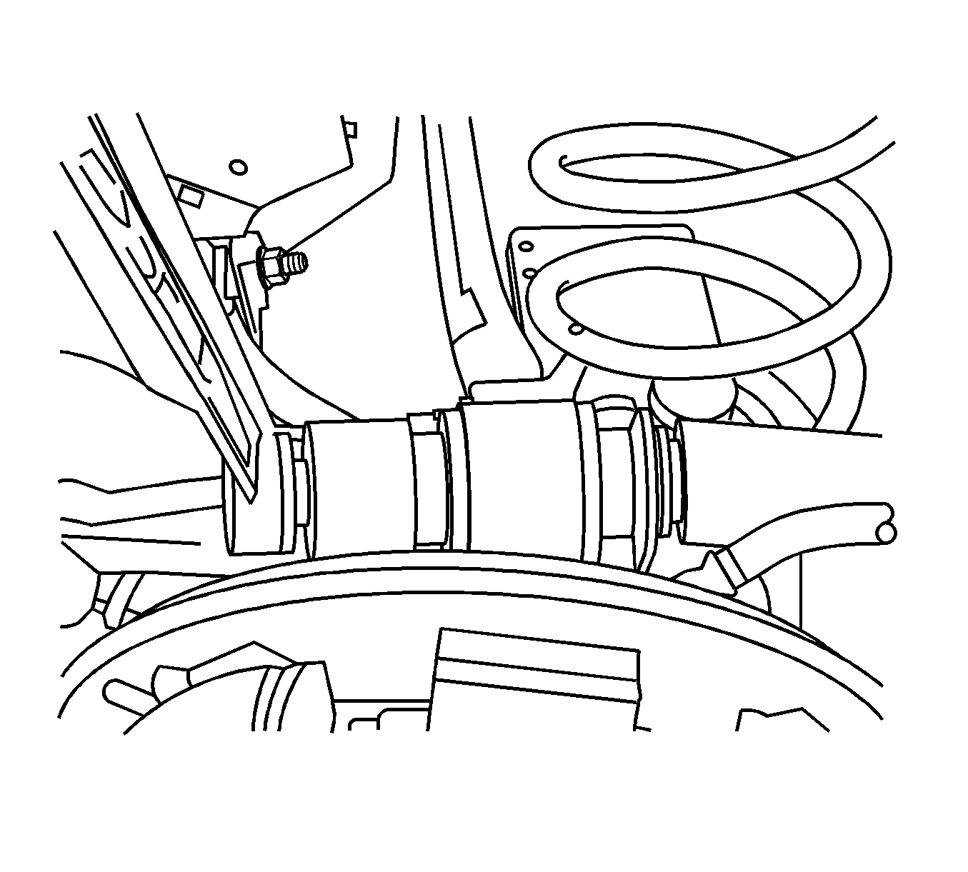
- Remove the upper control arm bolt and wheel speed sensor connector, if equipped, and position the upper control arm away from the brake hose to wheel cylinder connection.
- Remove the brake hose banjo bolt.
- Remove the brake hose from the wheel cylinder.
- Remove and discard the brake hose fitting gaskets.
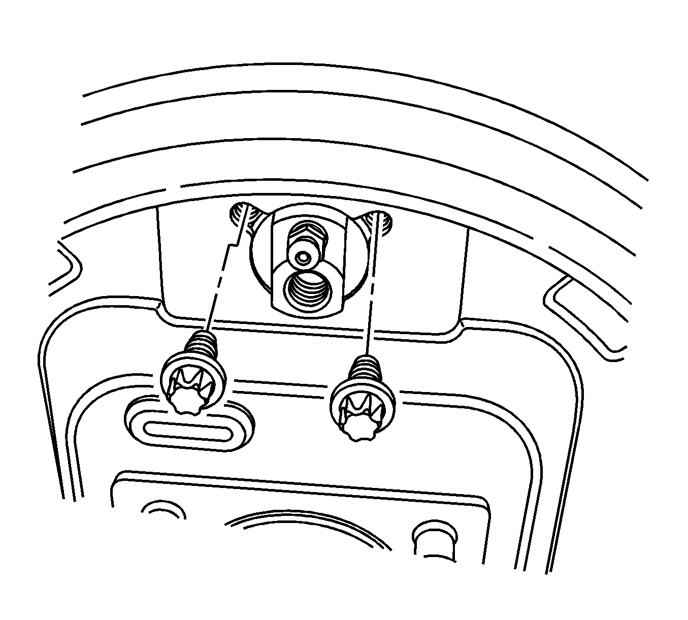
- Remove the wheel cylinder mounting bolts from the wheel cylinder.
- Using the J 38400 spread the brakes shoes, remove the wheel cylinder from the brake backing plate.
Caution: Refer to Brake Fluid Irritant Caution in the Preface section.
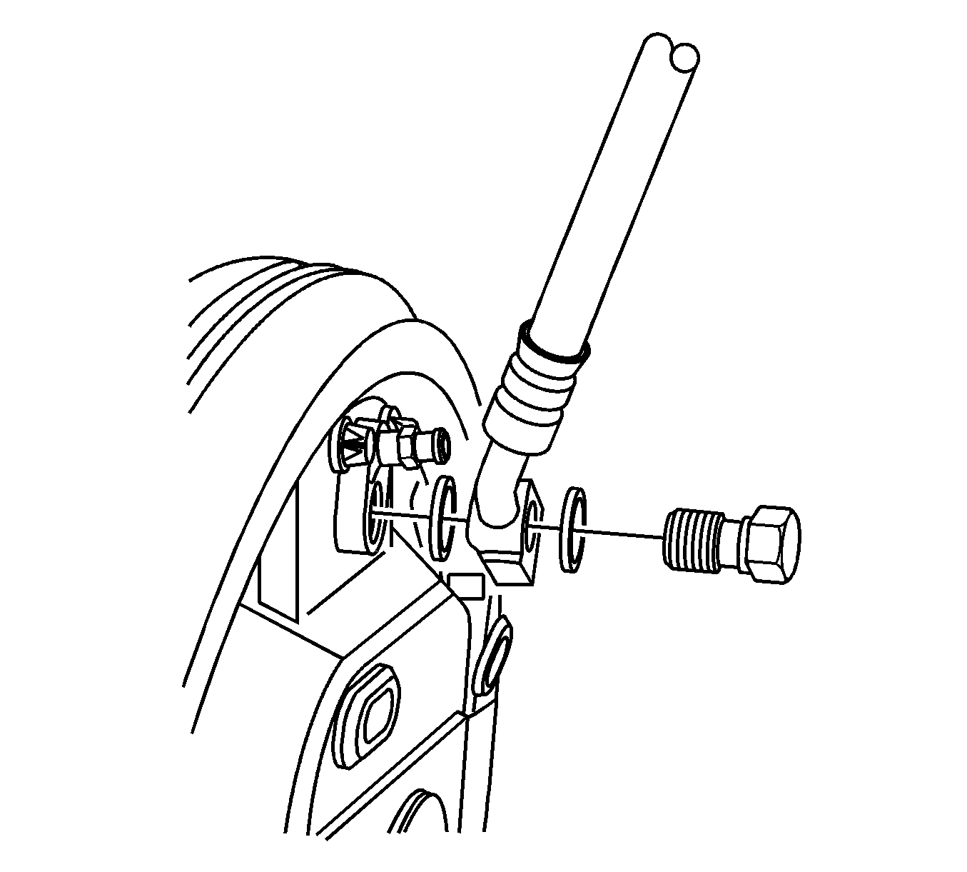
Important: Do not reuse the brake hose fitting gaskets.
Cap the brake hose fitting to prevent brake fluid leakage and contamination.
Installation Procedure
- Using the J 38400 spread the brakes shoes, position the wheel cylinder to the brake backing plate.
- Install the wheel cylinder mounting bolts.
- Assemble the 2 new brake hose fitting gaskets and the brake hose banjo bolt to the brake hose.
- Install the brake hose assembly to the wheel cylinder.
- Connect the wheel speed sensor connector if equipped with ABS and install the upper control arm bolt and nut.
- Install the brake drum. Refer to Brake Drum Replacement.
- Remove the jack stand from the lower control arm assembly.
- Bleed the hydraulic brake system. Refer to Hydraulic Brake System Bleeding.
- Install the tire and wheel assembly. Refer to Tire and Wheel Removal and Installation.
- Lower the vehicle.
- Check the rear alignment. Refer to Wheel Alignment Measurement.

Notice: Refer to Fastener Notice in the Preface section.

Tighten
Tighten the bolts to 10 N·m (89 lb in).

Tighten
Tighten the brake hose banjo bolt to 50 N·m (37 lb ft).

Tighten
Tighten the nut to 180 N·m (133 lb ft).


