For 1990-2009 cars only
Removal Procedure
- Remove the brake drum. Refer to Brake Drum Replacement .
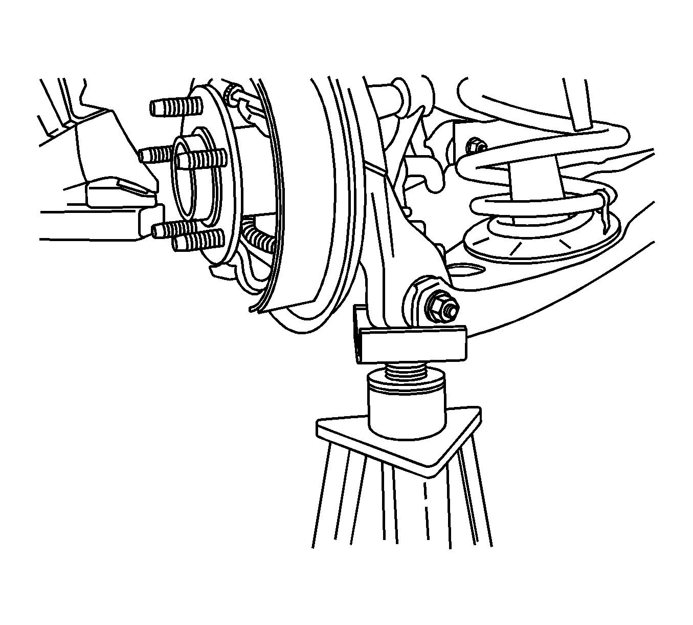
- Support the lower control arm assembly with a jack stand or suitable support fixture.
- Remove the brake shoes. Refer to Brake Shoe Replacement .
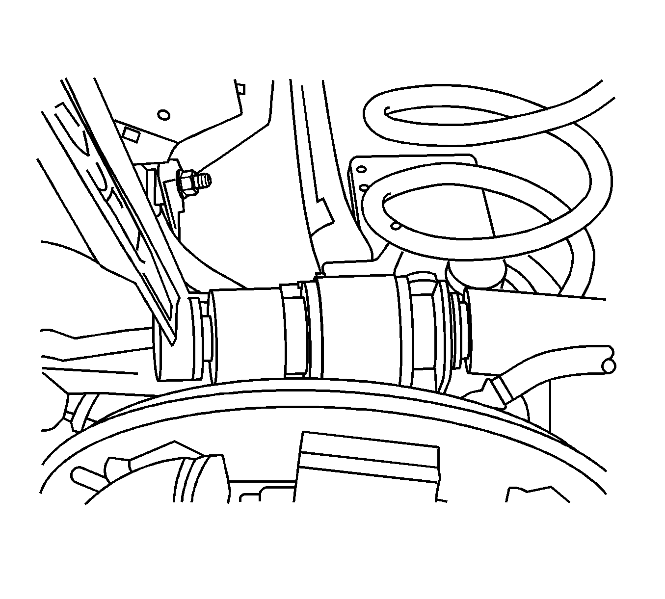
- Remove the universal spring.
- Remove the upper control arm bolt and wheel speed sensor connector if equipped with ABS and position the upper control arm away from the brake hose to wheel cylinder connection.
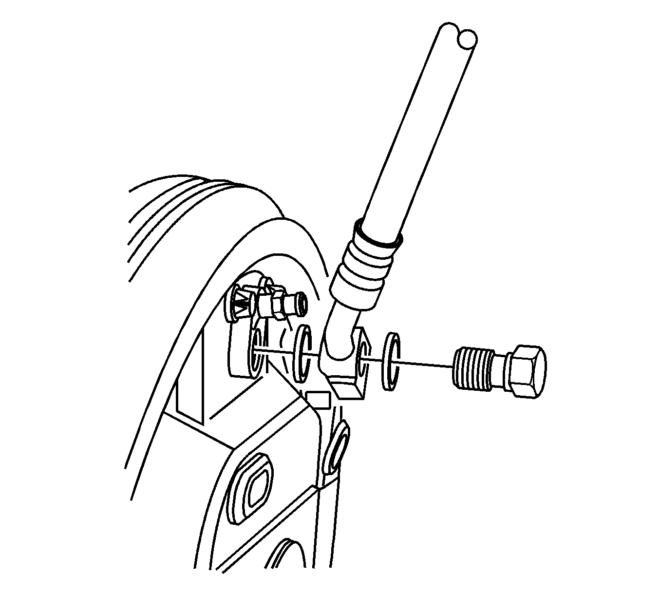
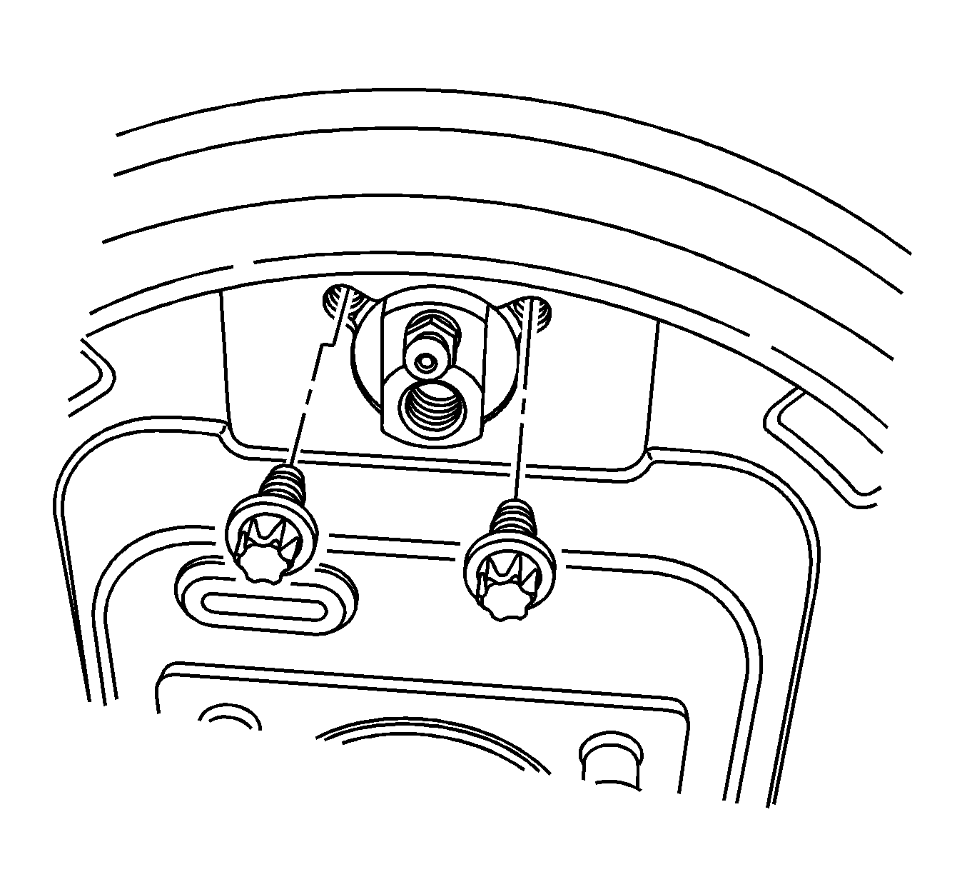
- Remove the brake hose banjo bolt and the 2 copper gaskets. Cap or plug the exposed brake hose to prevent fluid loss and contamination.
- Remove the wheel cylinder mounting bolts from the wheel cylinder and remove the wheel cylinder from the backing plate assembly.
- Remove the park brake cable from the park brake lever.
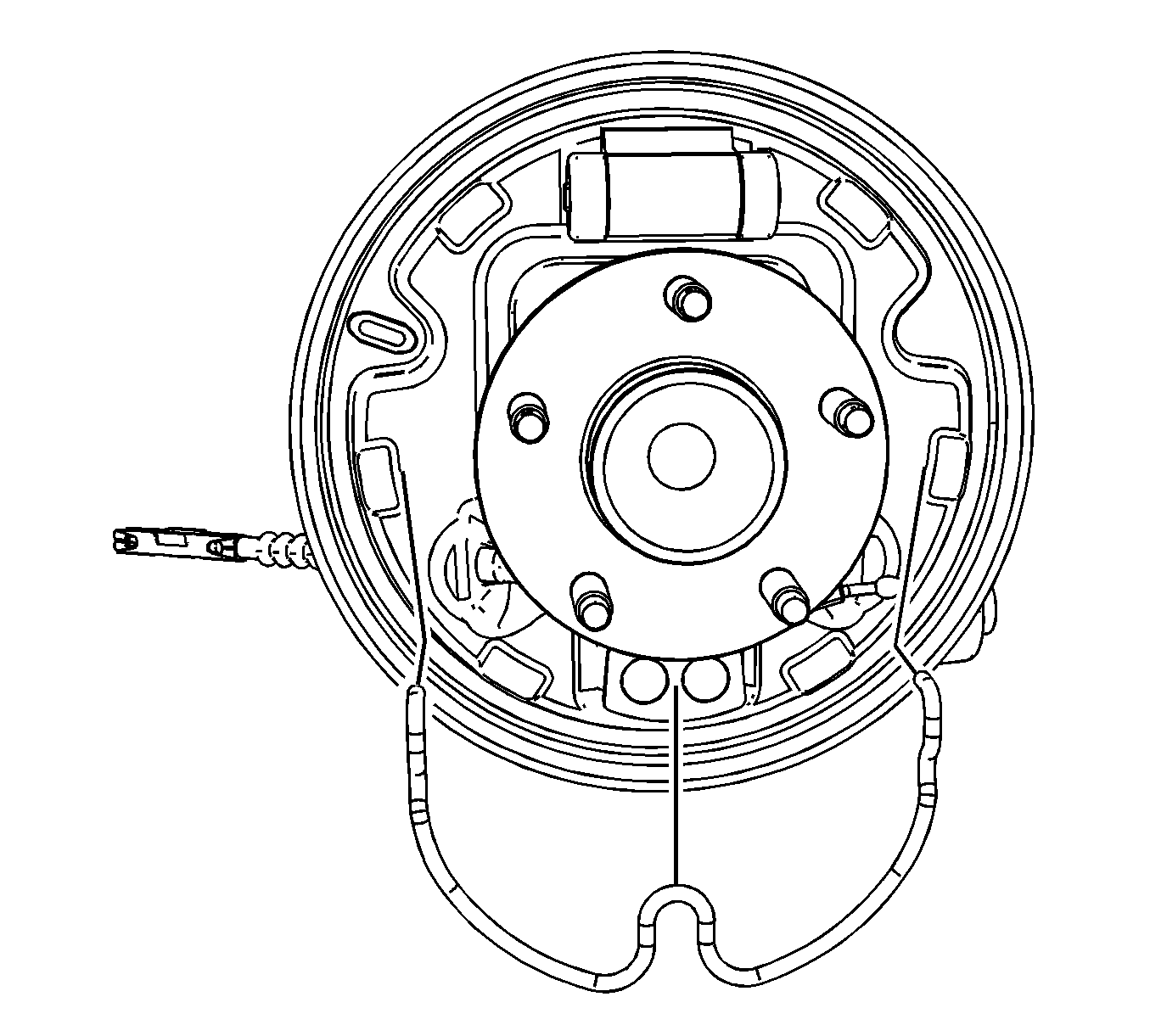
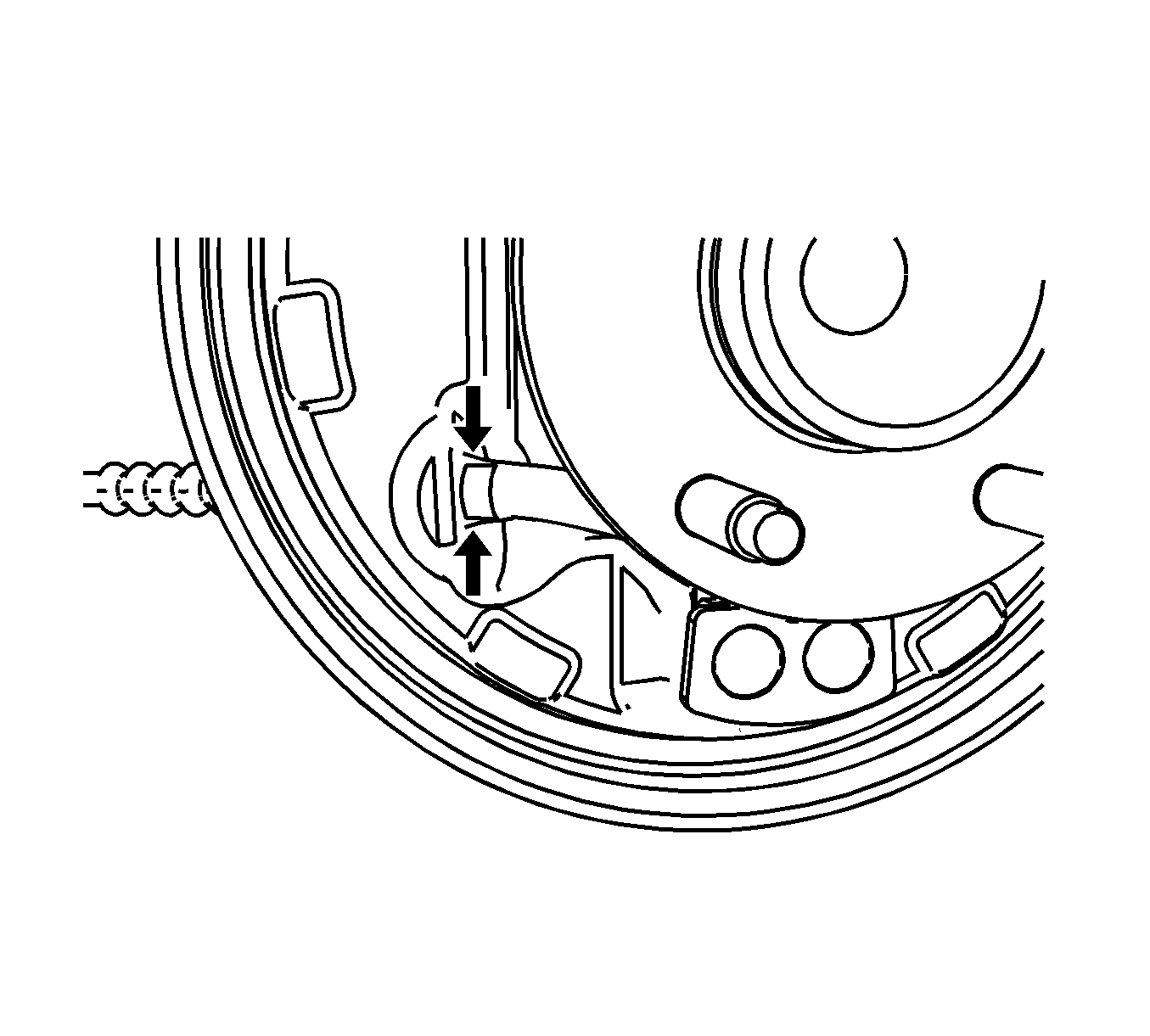
- Remove the park brake cable from the backing plate by depressing the locking tabs and pulling the cable out of the backing plate.
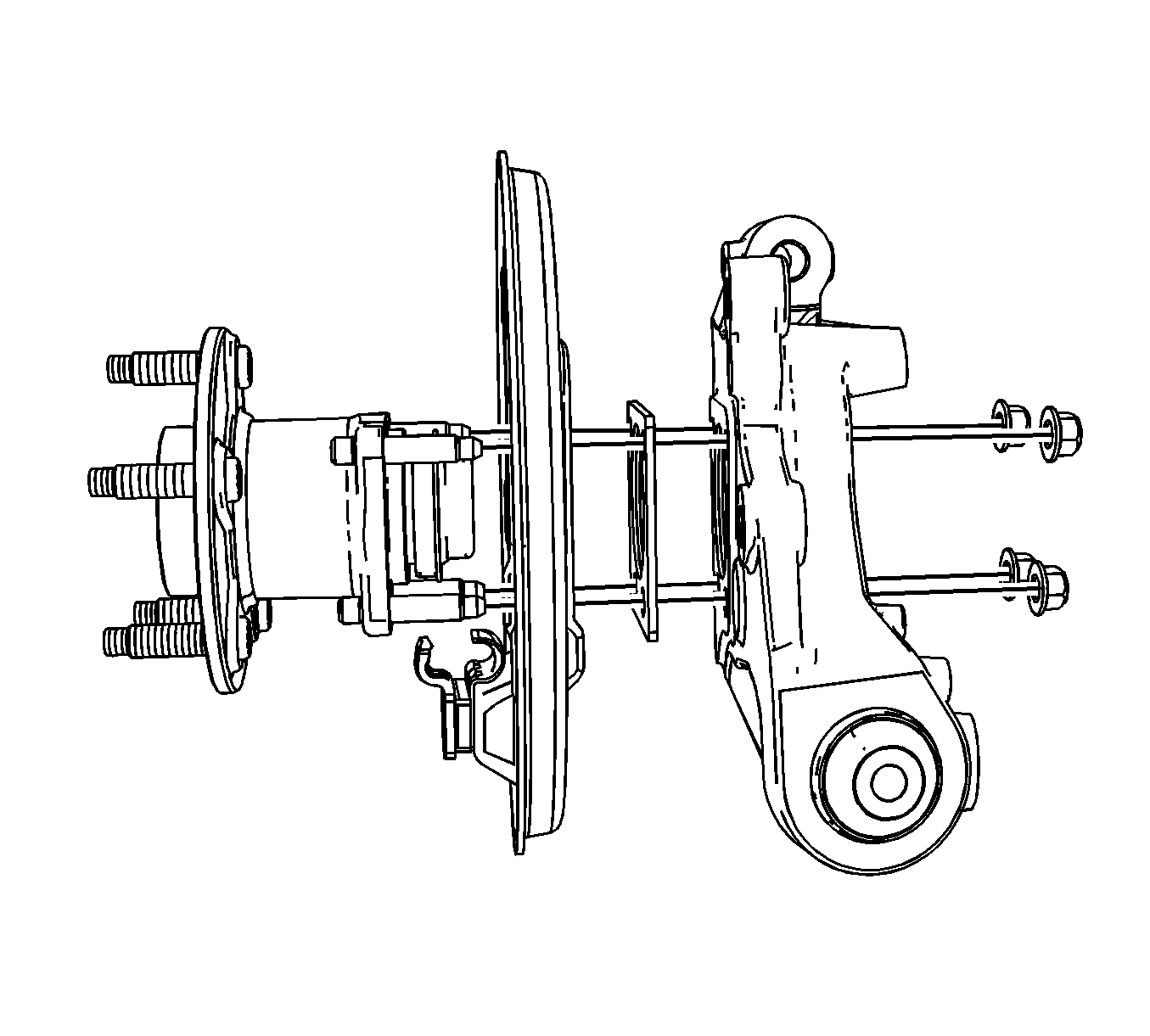
- Remove the 4 nuts securing the wheel bearing, backing plate assembly and the spacer plate to the knuckle.
- Remove the wheel bearing, backing plate assembly and the spacer plate from the knuckle.
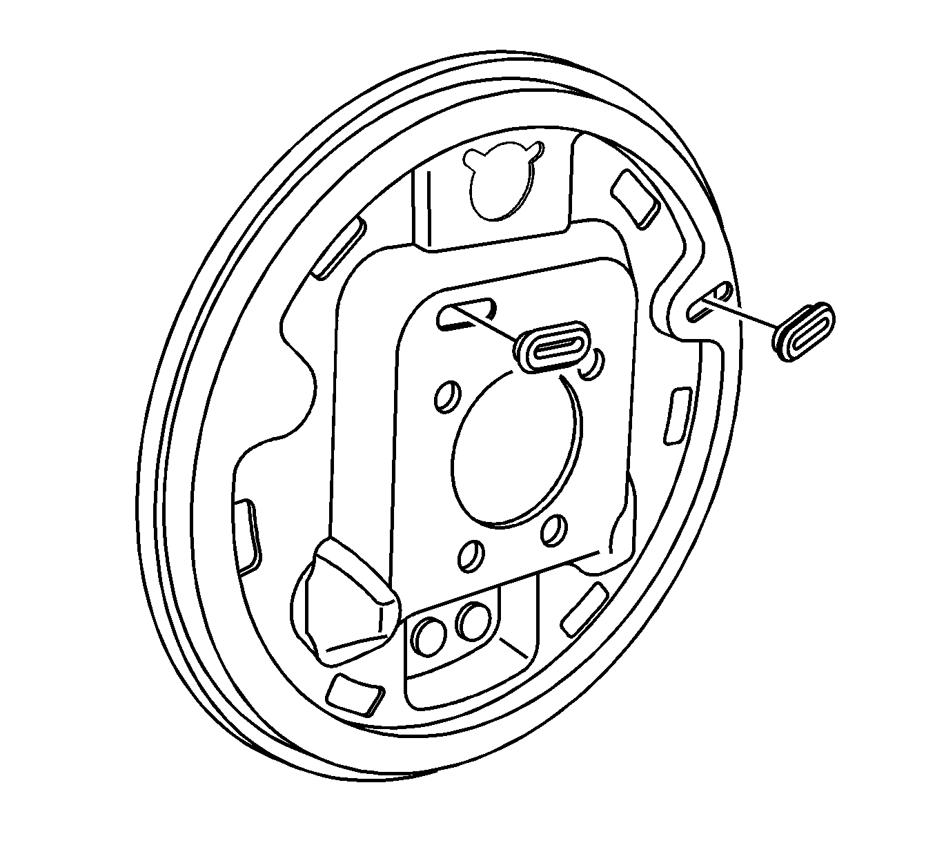
- Remove the backing plate plugs from the backing plate assembly.
Caution: Refer to Brake Dust Caution in the Preface section.
Installation Procedure
- Install the backing plate plugs into the new backing plate assembly.
- Install the wheel bearing, backing plate assembly and the spacer plate to the knuckle.
- Install the 4 nuts securing the wheel bearing, backing plate assembly and the spacer plate to the knuckle.
- Install the park brake cable to the backing plate assembly by pushing the cable thorough the backing plate assembly until the locking tabs click into place.
- Install the park brake cable to the park brake lever.
- Install the wheel cylinder to the backing plate assembly and install the wheel cylinder mounting bolts.
- Remove the cap or plug from the brake hose end.
- Install the brake hose banjo bolt and 2 new copper gaskets.
- Connect the wheel speed sensor connector if equipped with ABS brakes and install the upper control arm bolt and nut.
- Install the universal spring.
- Install the brake shoes. Refer to Brake Shoe Replacement .
- Remove the jack stand or suitable support fixture from the lower control arm assembly.
- Adjust the drum brakes. Refer to Drum Brake Adjustment .
- Install the brake drum. Refer to Brake Drum Replacement .
- Bleed the brake hydraulic system. Refer to Hydraulic Brake System Bleeding .
- Lower the vehicle.
- Check the rear alignment. Refer to Wheel Alignment Measurement .


Notice: Refer to Fastener Notice in the Preface section.
Tighten
Tighten the nuts to 63 N·m (47 lb ft).


Tighten
Tighten the bolts to 10 N·m (89 lb in).

Tighten
Tighten the banjo bolt to 50 N·m (37 lb ft).

Tighten
Tighten the nut to 180 N·m (133 lb ft).


