For 1990-2009 cars only
Removal Procedure
- Position the vehicle on a hoist and raise the vehicle. Refer to Lifting and Jacking the Vehicle .
- Remove the transaxle oil pan. Refer to Oil Pan Replacement .
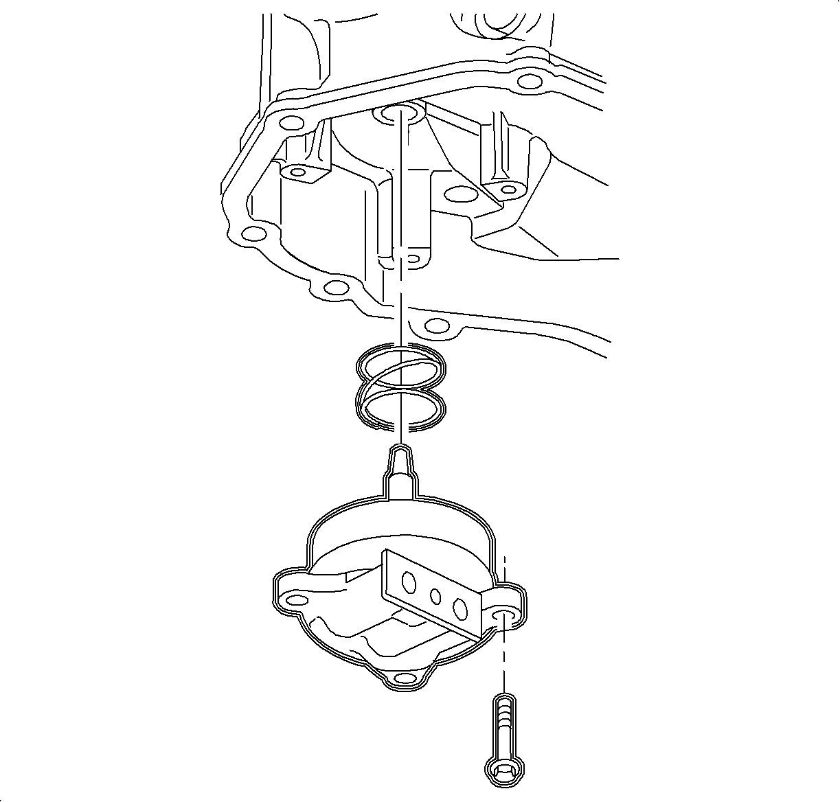
- Remove the oil feed pipe-to-low/reverse servo assembly bolt.
- Remove the low and reverse band servo cover assembly bolts.
- Pull the oil feed pipe away from the servo cover and remove the servo assembly.

Caution: Ensure that the vehicle is properly supported and squarely positioned. To help avoid personal injury when a vehicle is on a hoist, provide additional support for the vehicle on the opposite end from which the components are being removed.
Important: Remove servo cover bolts evenly to prevent damage to servo cover.
Disassembly Procedure
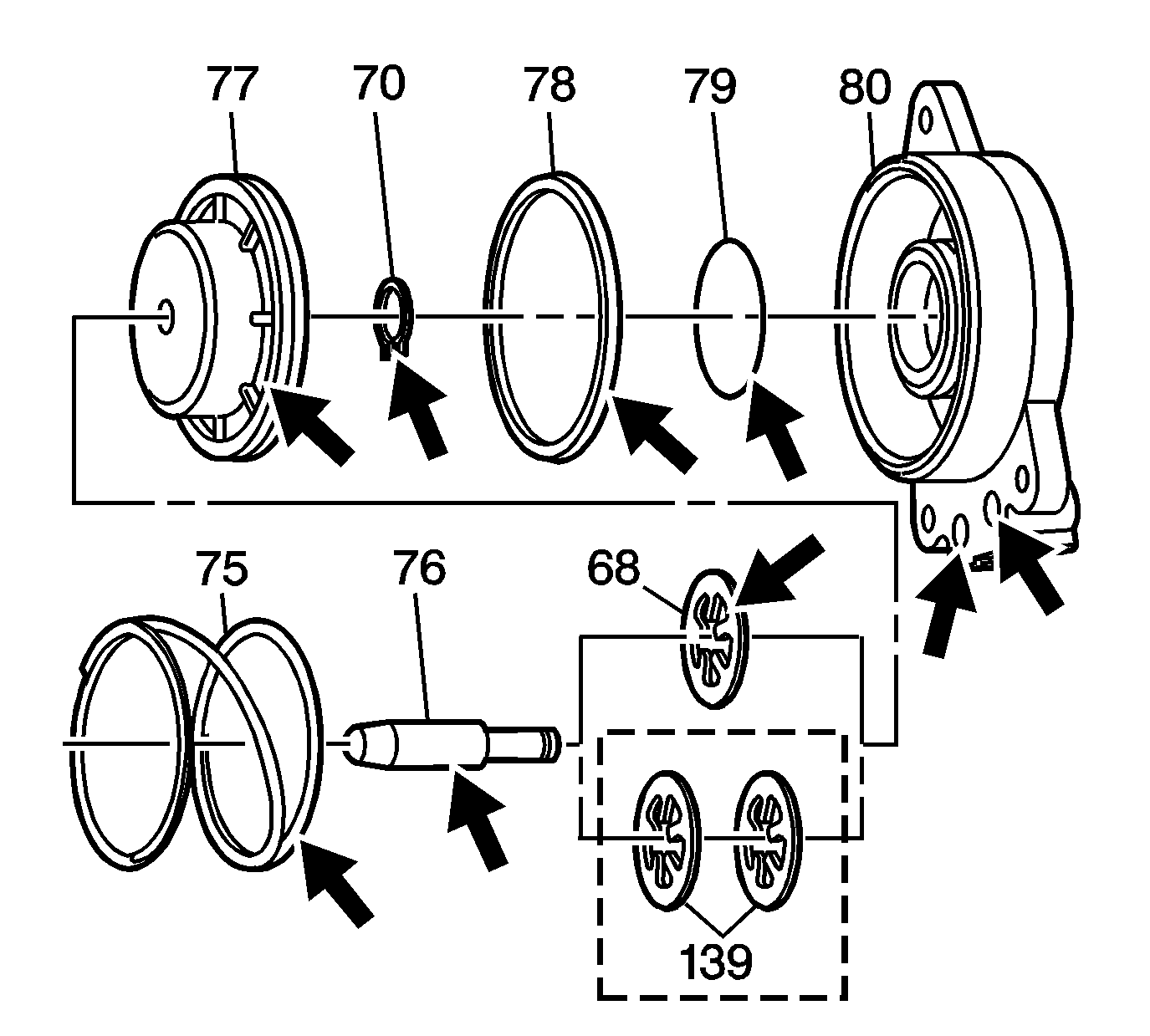
- Remove the piston pin assembly from the servo cover.
- Remove the snap ring (70) from the servo pin.
- Remove the piston (77) and the servo cushion springs (75)from the servo pin.
- Remove the servo piston seals from the cover (78, 79).
- Discard the servo piston seals.
- Inspect all components for damage.
- Inspect the fluid feed holes for the proper opening.
- Inspect the bolt hole threads for debris or stripping.
- Inspect the seal grooves for damage.
- Clean and dry each component.

Assembly Procedure
- Assemble the servo cushion springs (75) and the servo piston (77) onto the servo pin (76).
- Install the snap ring (70) onto the servo pin in order to retain the servo cushion springs and servo piston.
- Assemble new seals (78, 79) onto the servo piston and servo cover.
- Assemble the servo piston assembly into the servo cover. Lubricate the piston seals with transaxle fluid in order to aid in assembly.

Installation Procedure
- Install the servo return spring into the transaxle case.
- Install the servo cover and piston assembly over the servo return spring.
- Hand start and install the servo cover bolts.
- Install the oil pan. Refer to Oil Pan Replacement .
- Lower the vehicle.
- Remove the AIR. Refer to Transmission Fluid Check .
- Add DEXRON® VI transaxle fluid or equivalent to the specified refill capacity.
- Start the engine, warm up the transaxle, and check for leaks.
- Inspect for proper fluid level. Refer to Transmission Fluid Check .
- Reset the TAP values. Refer to Transmission Adaptive Functions .

Important: Hand start and tighten the servo cover bolts evenly to prevent damage to the servo cover bore.
Notice: Refer to Fastener Notice in the Preface section.
Tighten
Tighten the servo cover bolts to 12 N·m (9 lb ft).
Specification
| • | The bottom pan removal capacity is approximately 6.5 L (6.9 qt). |
| • | The complete overhaul capacity is approximately 9 L (9.5 qt). |
| • | The dry capacity is approximately 12.2 L (12.9 qt). |
Important: It is recommended that transmission adaptive pressure (TAP) information be reset.
Resetting the TAP values using a scan tool will erase all learned values in all cells. As a result, The ECM, PCM or TCM will need to relearn TAP values. Transmission performance may be affected as new TAP values are learned.