For 1990-2009 cars only
Removal Procedure
- Remove battery tray assembly assembly. Refer to Battery Tray Replacement.
- Remove the PNP switch. Refer to Park/Neutral Position Switch Replacement.
- Remove the transmission upper side cover bolts.
- Install the engine support fixture. Refer to Engine Support Fixture.
- Raise the vehicle. Refer to Lifting and Jacking the Vehicle.
- Remove the left front tire and wheel. Refer to Tire and Wheel Removal and Installation.
- Remove the left lower control arm. Refer to Lower Control Arm Replacement.
- Remove the wheel drive shaft from the transmission. Refer to Wheel Drive Shaft Replacement.
- Disconnect the steering rack intermediate shaft. Refer to Steering Gear Replacement.
- Remove the frame. Refer to Frame Replacement.
- On vehicles equipped with the L61 engine, remove the transmission mount. Refer to Transmission Mount Replacement - Left Side.
- Lower the vehicle.
- Lower the LH side of the engine with the engine support fixture to allow the transmission side cover enough room to get past the left rail.
- Raise the vehicle.
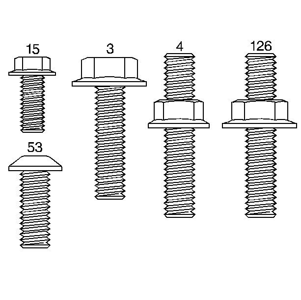
- Remove the 11 transmission side cover bolts (3) or Studs (4) (model dependant).
- Remove the transmission side cover (1).
- Remove the two side cover gaskets (5 and 6) and the side cover to driven support thrust washer (7). They may remain with the side cover. Only replace if necessary.
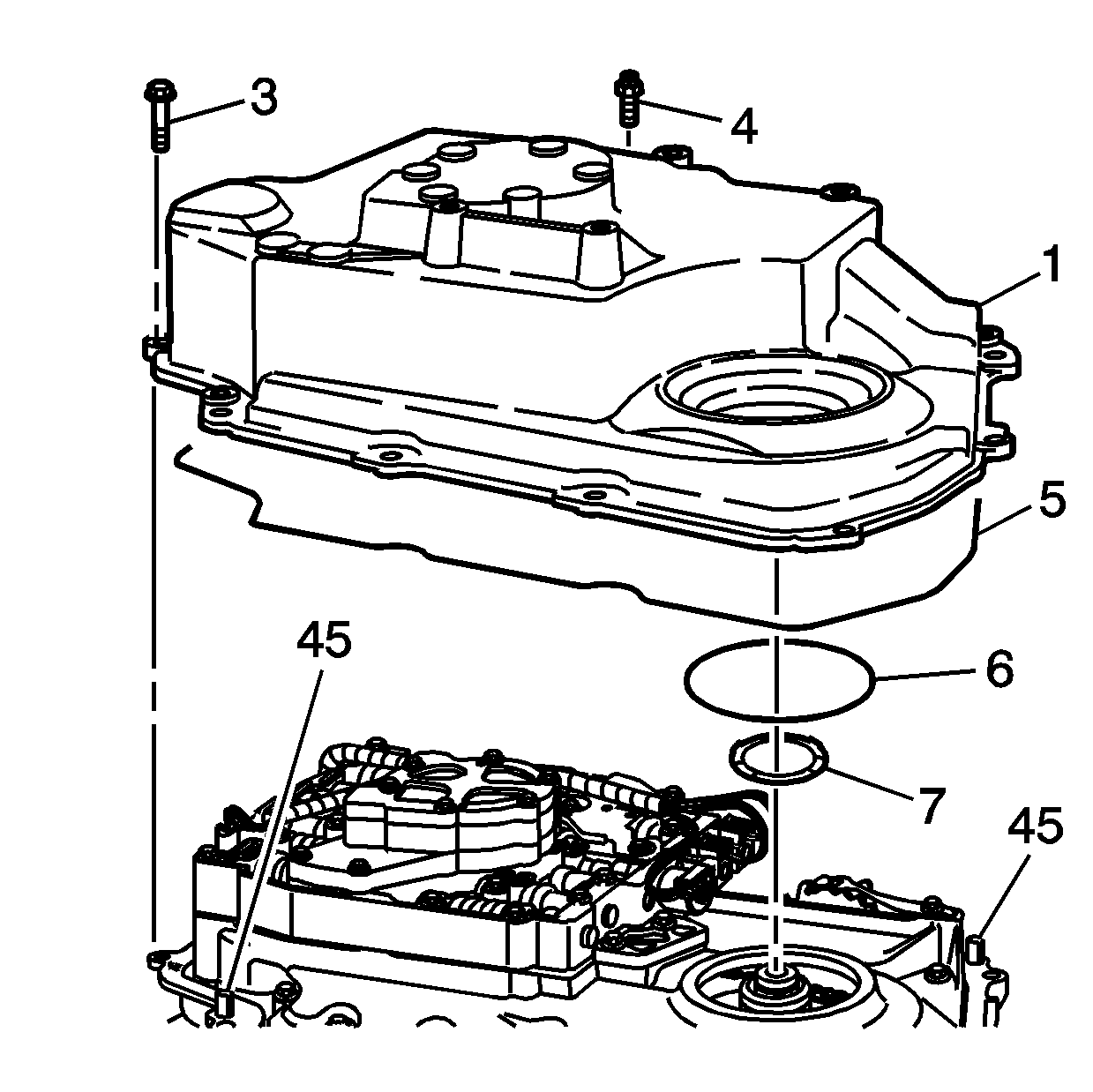
Notice: Pry on the corner of the case side cover near the locating dowel pins (45), to prevent damage to the sealing surfaces.
Installation Procedure
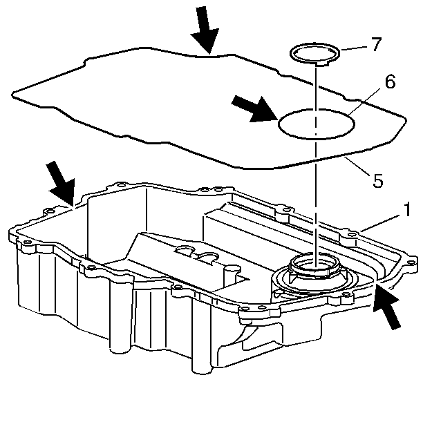
- If the seals were removed, thoroughly clean and dry the side cover seal grooves and the side cover seals.
- Install the side cover gaskets (5 and 6) into the grooves on the side cover (1).
- Retain the seals with J 36850 or equivalent.
- Install the side cover to drive sprocket thrust washer (7) onto the side cover.
- Retain the thrust washer with J 36850 or equivalent.
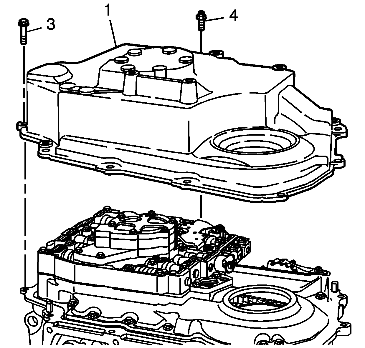
- Install the side cover assembly onto the transmission case.
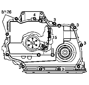
- Install the 11 side cover bolts (3) or studs (4) (model dependent).
- Refer to the graphic in order to find the correct installation points of the bolts and the stud.
- Hand start the bolts.
- Lower the vehicle.
- Raise the engine with the engine support fixture.
- Raise the vehicle. Refer to Lifting and Jacking the Vehicle.
- On vehicles equipped with the L61 engine, install the transmission mount. Refer to Transmission Mount Replacement - Left Side.
- Install the frame. Refer to Frame Replacement.
- Install the power steering intermediate shaft and tie-rod ends. Refer to Steering Gear Replacement.
- Install the wheel drive shaft to the transmission. Refer to Wheel Drive Shaft Replacement.
- Install the left lower control arm to the subframe and steering knuckle. Refer to Lower Control Arm Replacement.
- Install the left front tire and wheel. Refer to Tire and Wheel Removal and Installation.
- Lower the vehicle.
- Remove the engine support fixture. Refer to Engine Support Fixture.
- Install the PNP switch. Refer to Park/Neutral Position Switch Replacement.
- Install the battery tray assembly. Refer to Battery Tray Replacement.
- Fill the transmission. Refer to Approximate Fluid Capacities.
Notice: Refer to Fastener Notice in the Preface section.
Tighten
Tighten the side cover bolts and stud to 28 N·m (22 lb ft).
