Special Tools
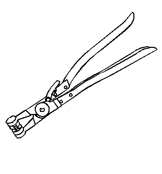
| • | J 38185 Hose Clamp Pliers |
| • | J 43828 Ball Joint Remover |
| • | J 44015 Steering Linkage Installer |
| • | J 45059 Torque Angle Meter |
Removal Procedure
- Remove the air cleaner outlet duct. Refer to Air Cleaner Outlet Duct Replacement.
- Relieve the fuel system pressure. Refer to Fuel Pressure Relief.
- Remove the air cleaner assembly. Refer to Air Cleaner Assembly Replacement.
- Disconnect the fuel feed pipe (1) quick connect fitting at the fuel rail. Refer to Metal Collar Quick Connect Fitting Service.
- Disconnect the evaporative emission (EVAP) line (3) quick connect fitting from the EVAP purge solenoid. Refer to Plastic Collar Quick Connect Fitting Service.
- Remove the fuel feed pipe clip (2) from the fuel line bracket.
- Remove the battery tray. Refer to Battery Tray Replacement.
- LAT only, remove the generator starter. Refer to Generator with Starter Replacement.
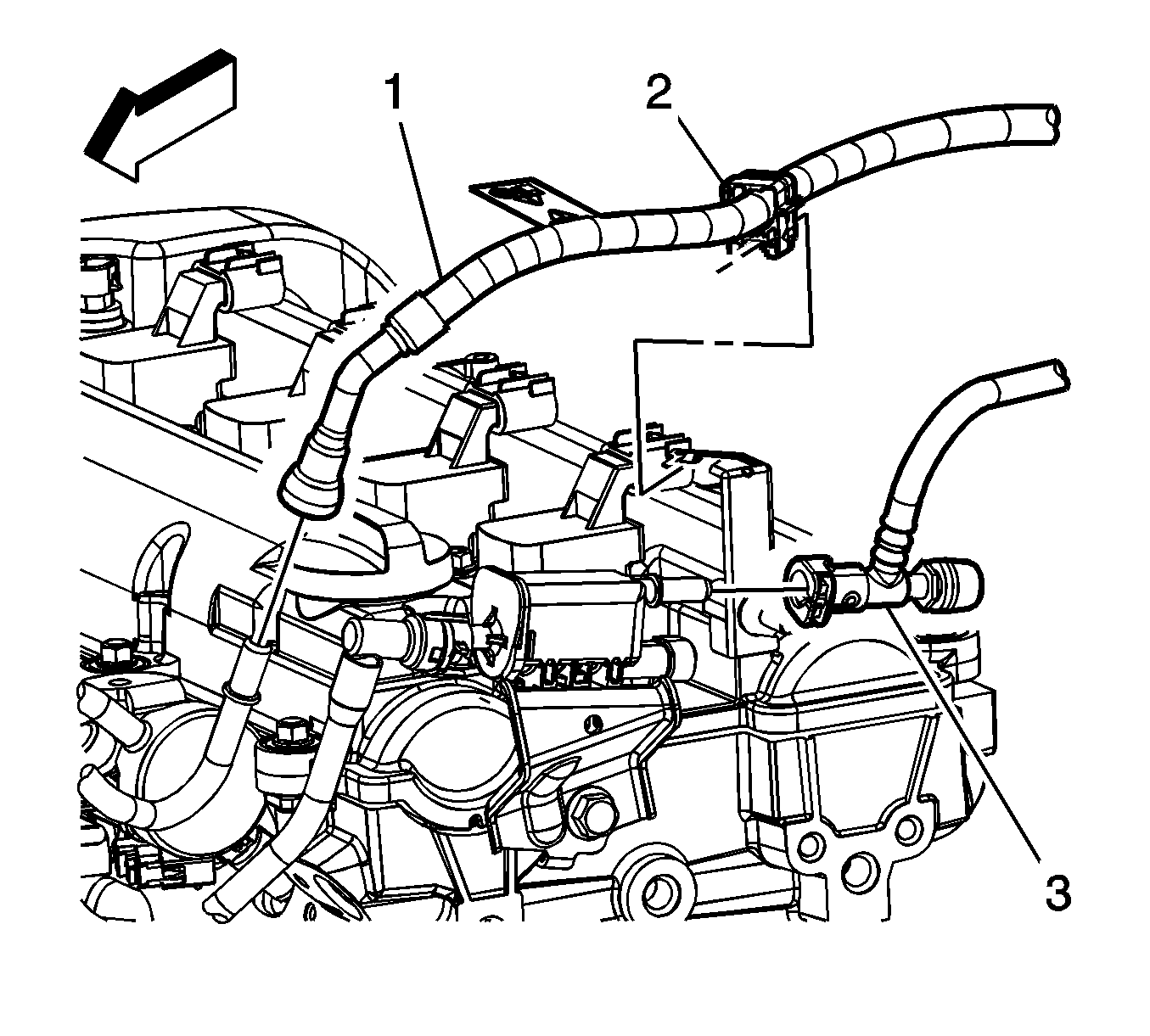
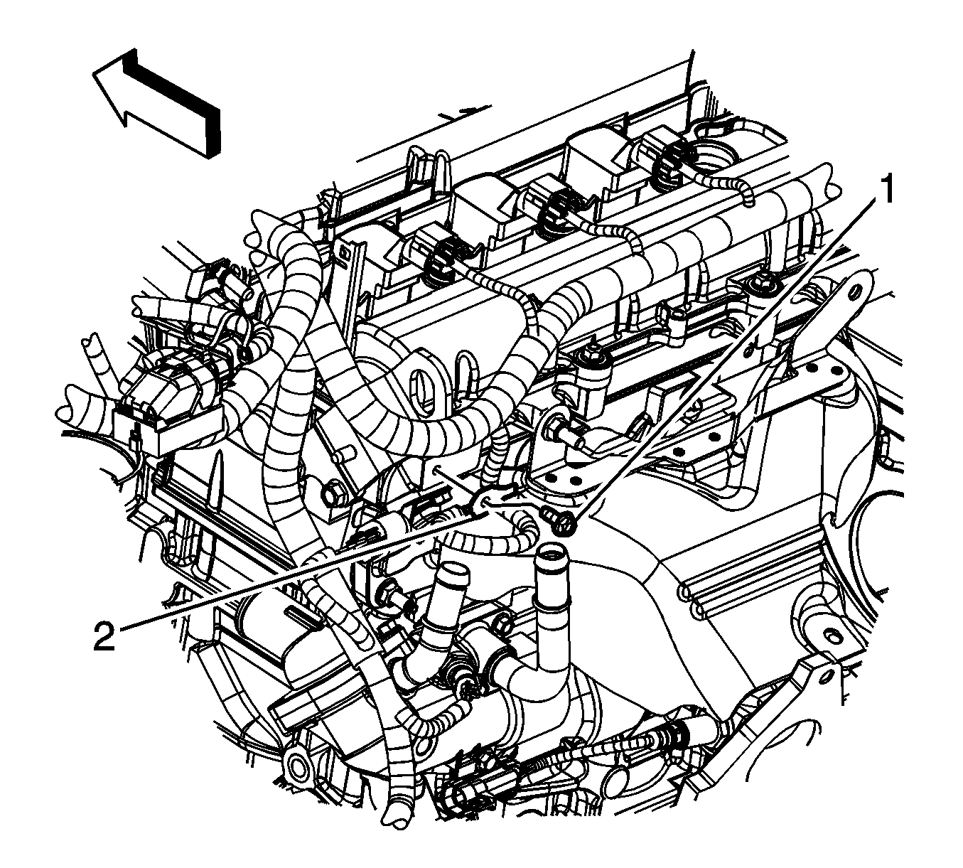
- Reposition the vacuum brake booster hose clamp (1) at the intake manifold.
- Remove the vacuum brake booster hose (2) from the intake manifold. Reposition the brake booster hose out of the way.
- Remove the coolant recovery inlet hose clamp (2) at the cylinder head.
- Remove the coolant recovery inlet pipe clip from the fuel rail.
- Remove the coolant recovery inlet hose (1) from the cylinder head. Reposition the hose/pipe out of the way.
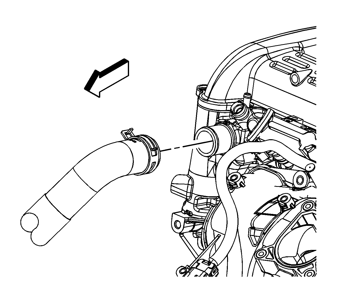
- Reposition the radiator inlet hose clamp using the J 38185 .
- Remove the radiator inlet hose from the cylinder head.
- Remove the radiator outlet hose. Refer to Radiator Outlet Hose Replacement.
- LAT only, reposition the generator control module coolant hose clamp (1) at the generator control module.
- LAT only, remove the generator control module coolant hose from the generator control module.
- LAT only, disconnect the engine wiring harness electrical connector (1) from the transaxle auxiliary pump module.
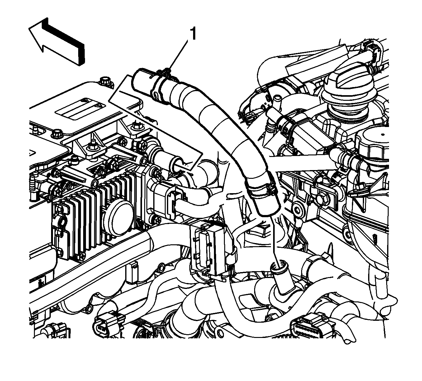
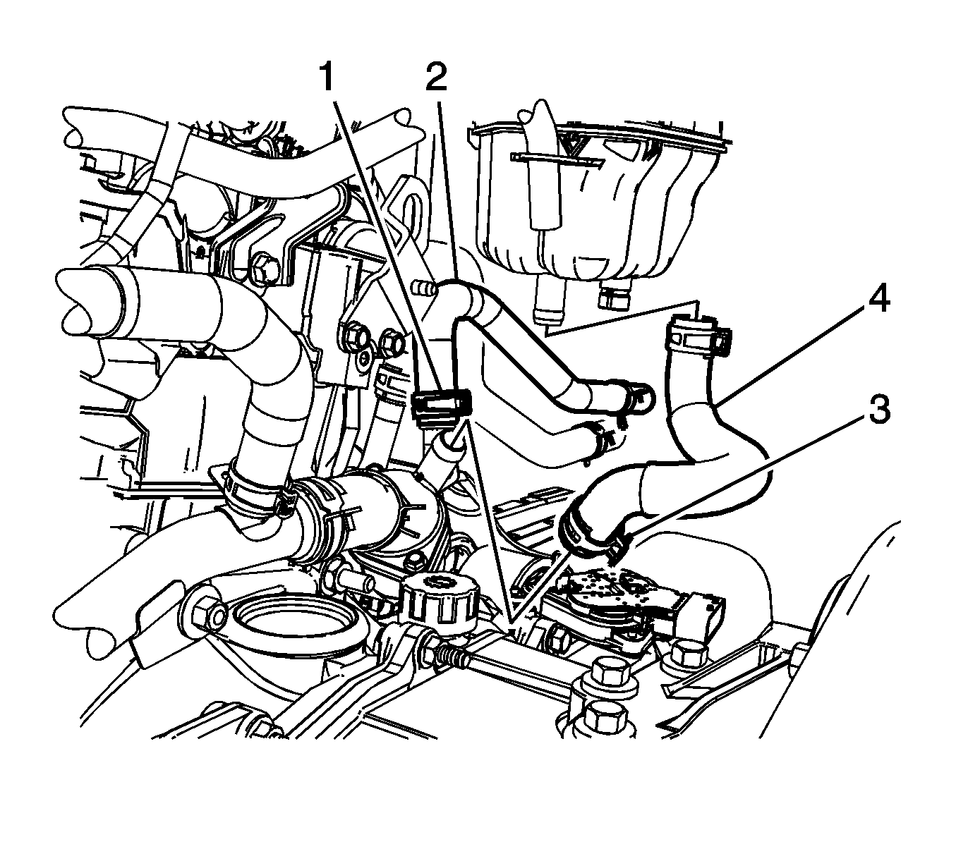
- Reposition the heater inlet hose clamp (1) at the thermostat housing.
- Remove the heater inlet hose (2) from the thermostat housing.
- Reposition the coolant recovery reservoir/heater inlet hose (3) clamp at the thermostat housing.
- Remove the coolant recovery reservoir/heater inlet hose (4) from the thermostat housing.
- Raise and support the vehicle. Refer to Lifting and Jacking the Vehicle.
- Drain the engine oil. Refer to Engine Oil and Oil Filter Replacement.
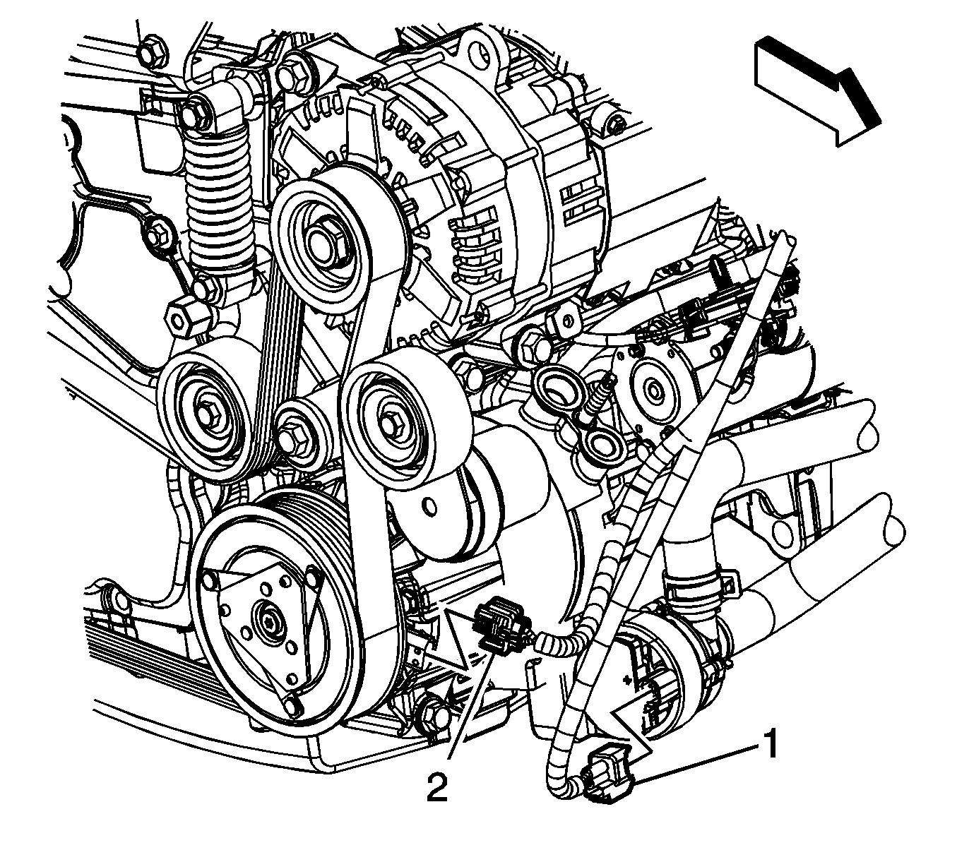
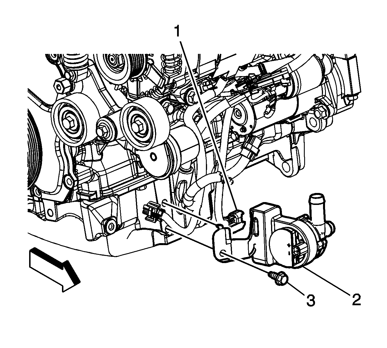
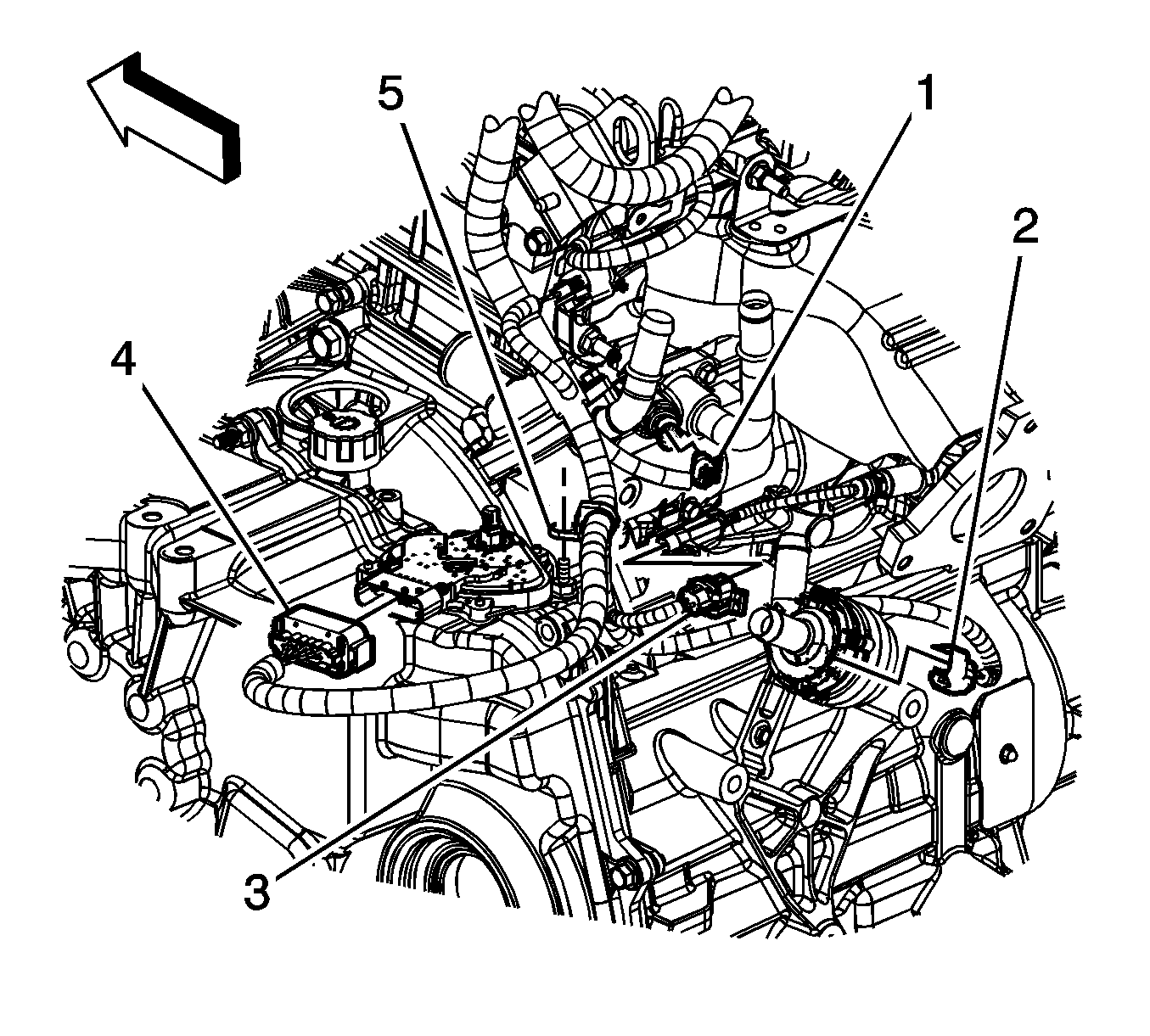
- LAT only, disconnect the engine wiring harness electrical connector (1) from the generator control module coolant pump.
- LAT only, disconnect the engine wiring harness electrical connector (2) from the air conditioning (A/C) compressor.
- LAT only, remove the generator control module coolant pump bolt (3) and pump (2).
- Unbolt the A/C compressor and reposition out of the way.
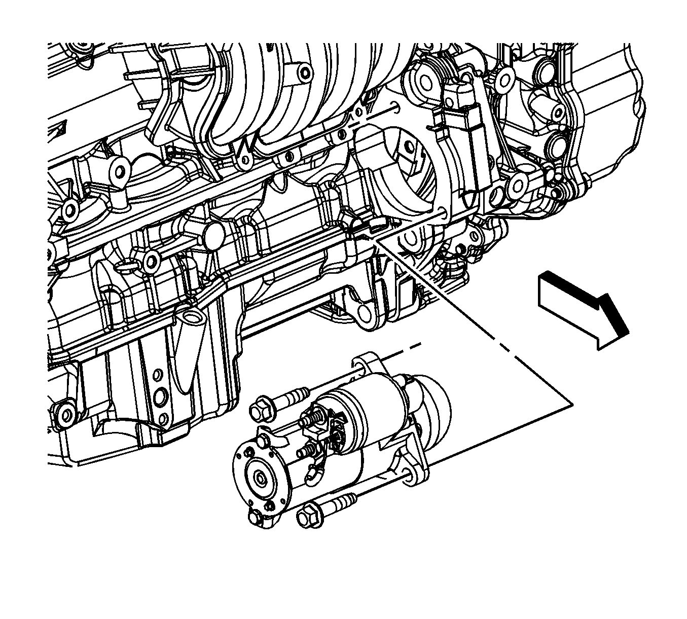
- Remove the positive battery cable to starter motor nut (4).
- Remove the positive battery cable lead (1) from the starter motor.
- Remove the positive battery cable from in between the starter and the engine. Reposition the positive battery cable out of the way.
- Remove the negative cable from the engine stud.
- LE5 only:
- LAT only, disconnect the engine wiring harness electrical connector (2) from the auxiliary heater water pump.
- LAT only, remove the auxiliary heater water pump bolt and pump.
- Lower the vehicle.
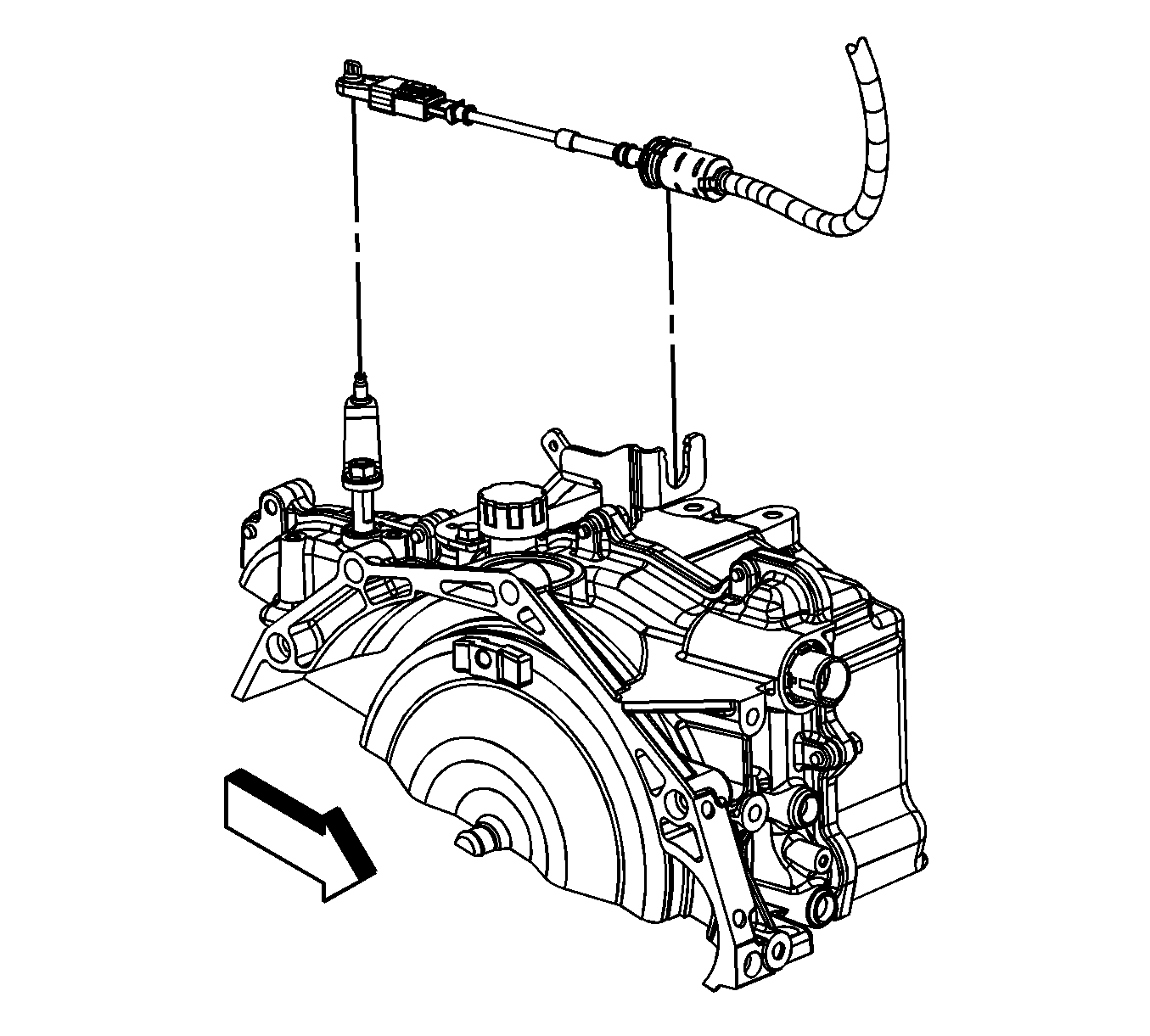
- Remove the transaxle shift cable from the range select lever.
- Release the shift control cable retaining clip and remove the cable from the shift control cable bracket.
- Using long tie straps, secure the radiator/condenser/fan assembly to the radiator support.
- Raise the vehicle.
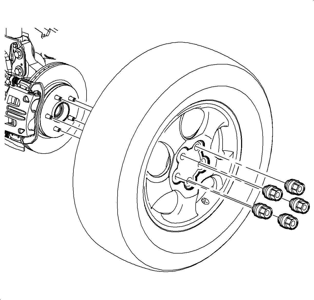
- Remove the front wheels and tires. Refer to Tire and Wheel Removal and Installation.
- Remove the right and left engine splash shields. Refer to Engine Splash Shield Replacement - Left Side and Engine Splash Shield Replacement - Right Side.
- Install a piece of hardwood 1 x 2 x 4 between the transaxle and the frame.
- Install a piece of hardwood 1 x 2 x 4 between the oil pan and the frame.
- Drain the transaxle fluid.
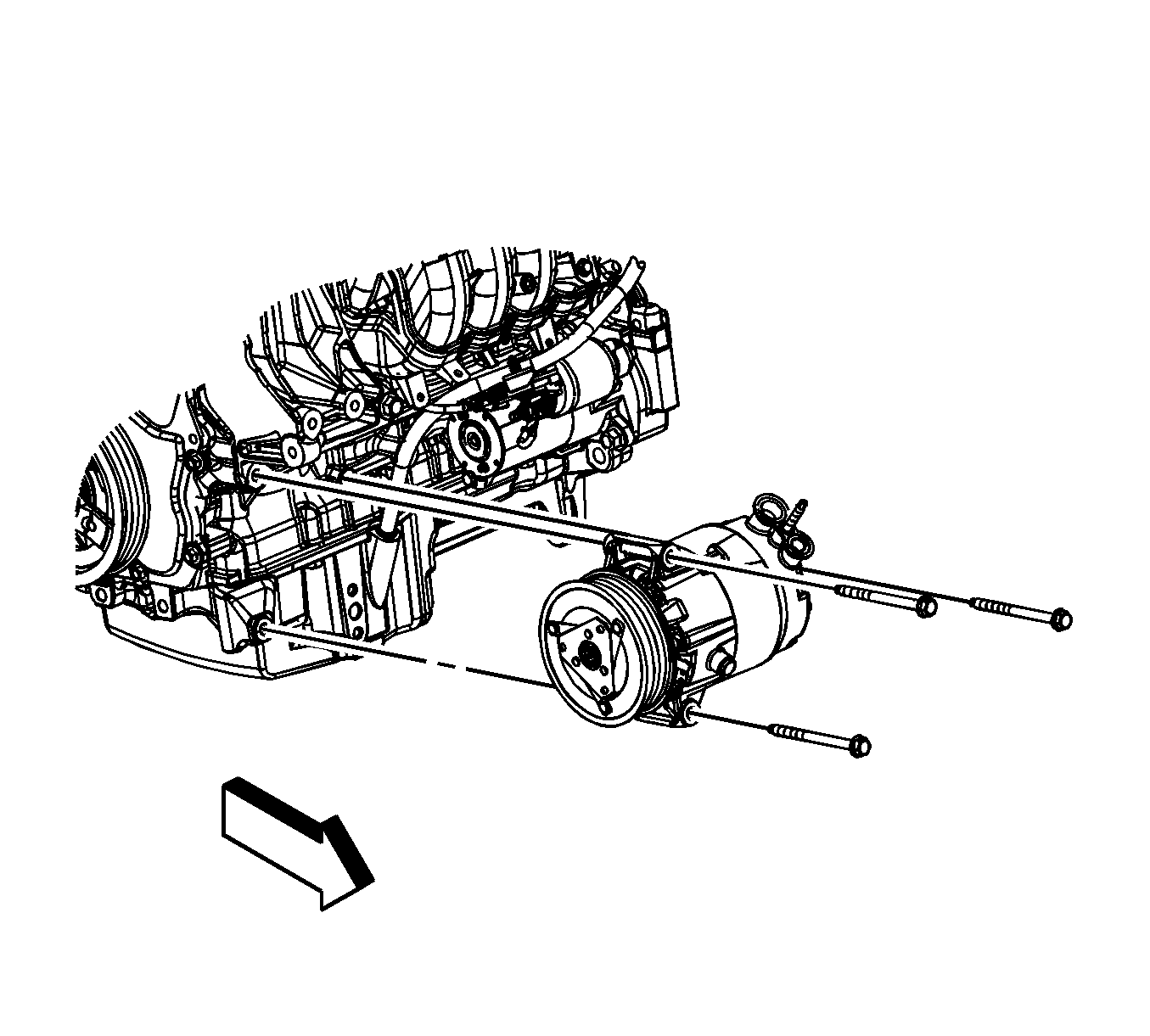
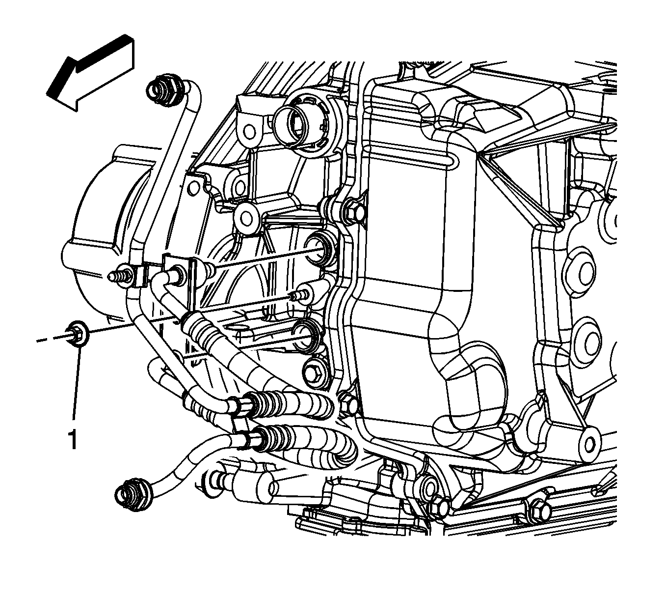
- If equipped with the 4T45, remove the transaxle oil cooler line to transaxle nut (1).
- If equipped with the 4T45, remove the transaxle oil cooler lines from the transaxle.
- If equipped with the 6T40, remove the fluid cooler lines at the transmission. Refer to Fluid Cooler Inlet Hose Replacement and Fluid Cooler Outlet Hose Replacement.
- Remove the exhaust manifold. Refer to Exhaust Manifold Replacement.
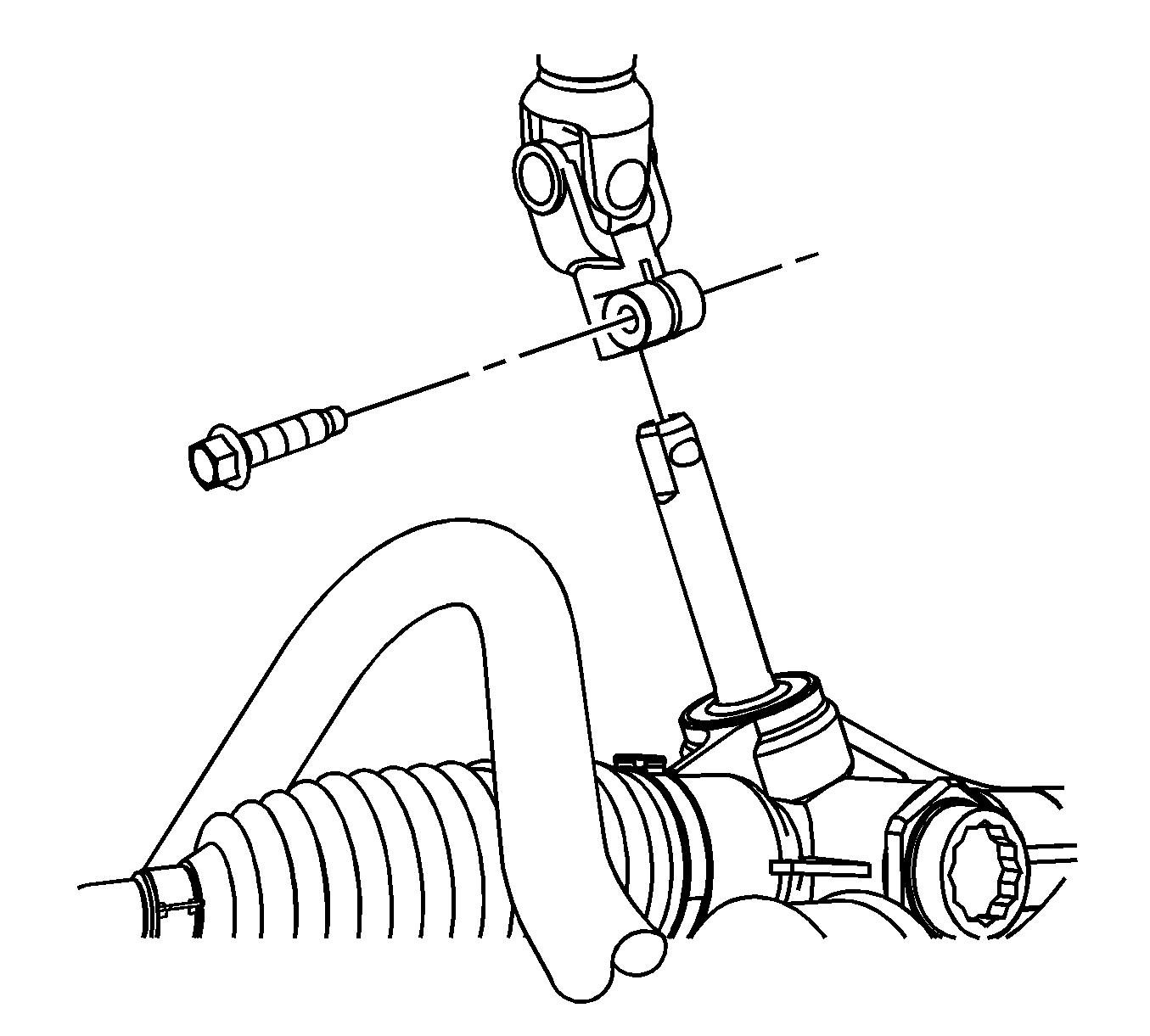
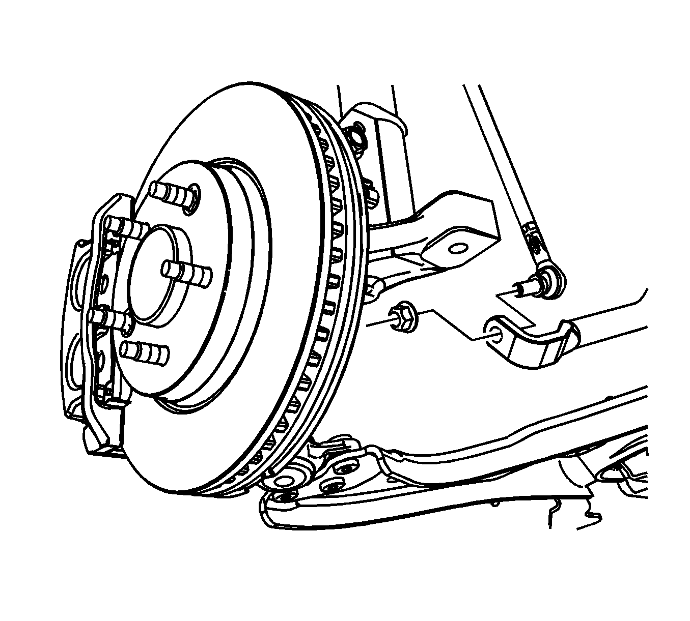
- Remove the intermediate to steering gear pinch bolt and disconnect the intermediate shaft from the steering gear. Discard the pinch bolt.
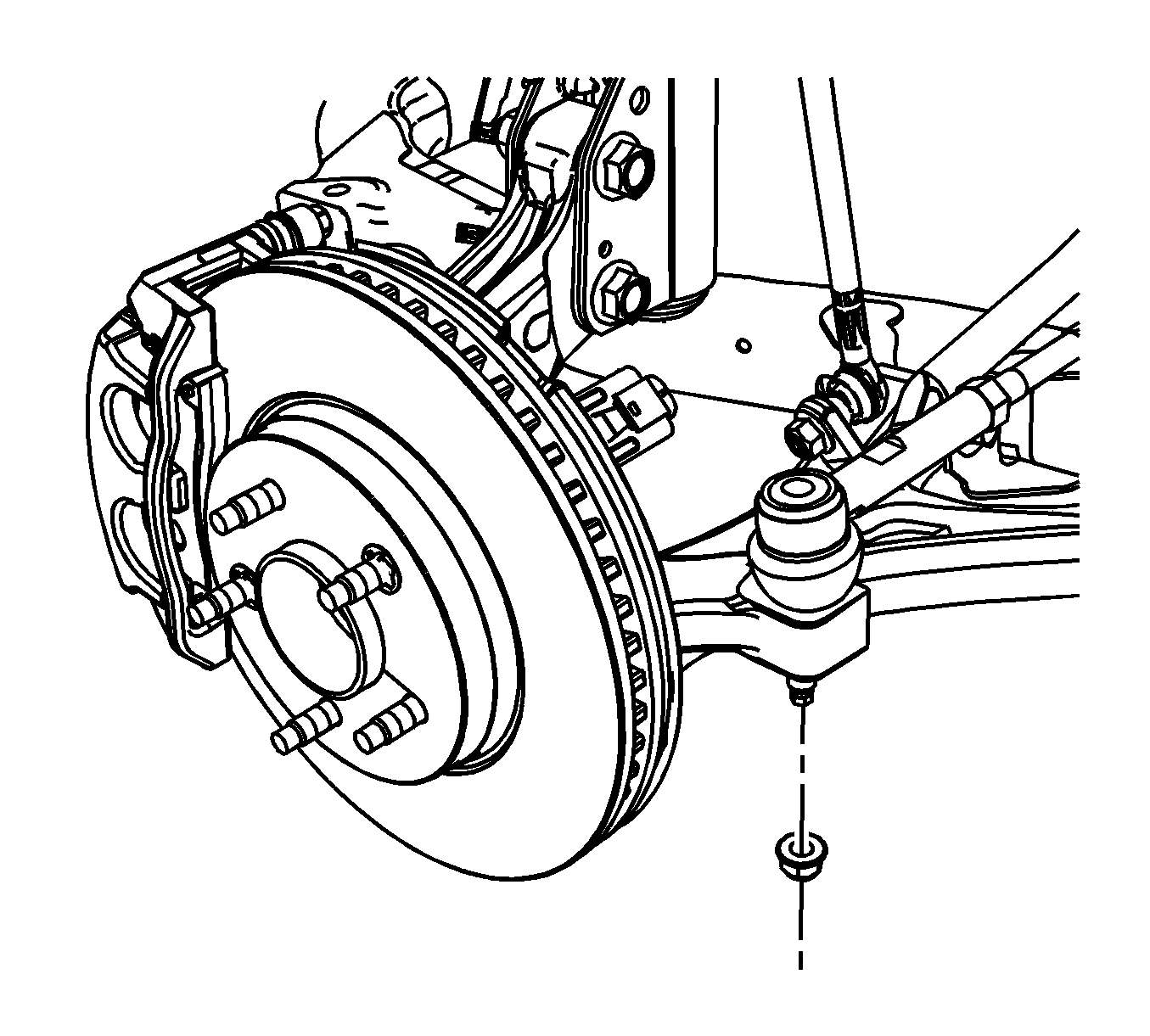
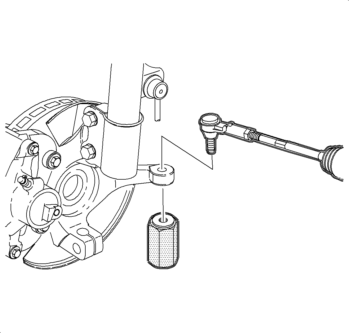
- Remove and discard both outer tie rod to steering knuckle nuts.
- Separate the tie rods from the steering knuckles. Refer to Steering Linkage Outer Tie Rod Replacement
- Remove the stabilizer link to stabilizer shaft nuts and disconnect the stabilizer links from the stabilizer shaft.
- Prior to removal, note the orientation of the lower control arm ball stud to the steering knuckle pinch bolt and remove the pinch bolt and discard.
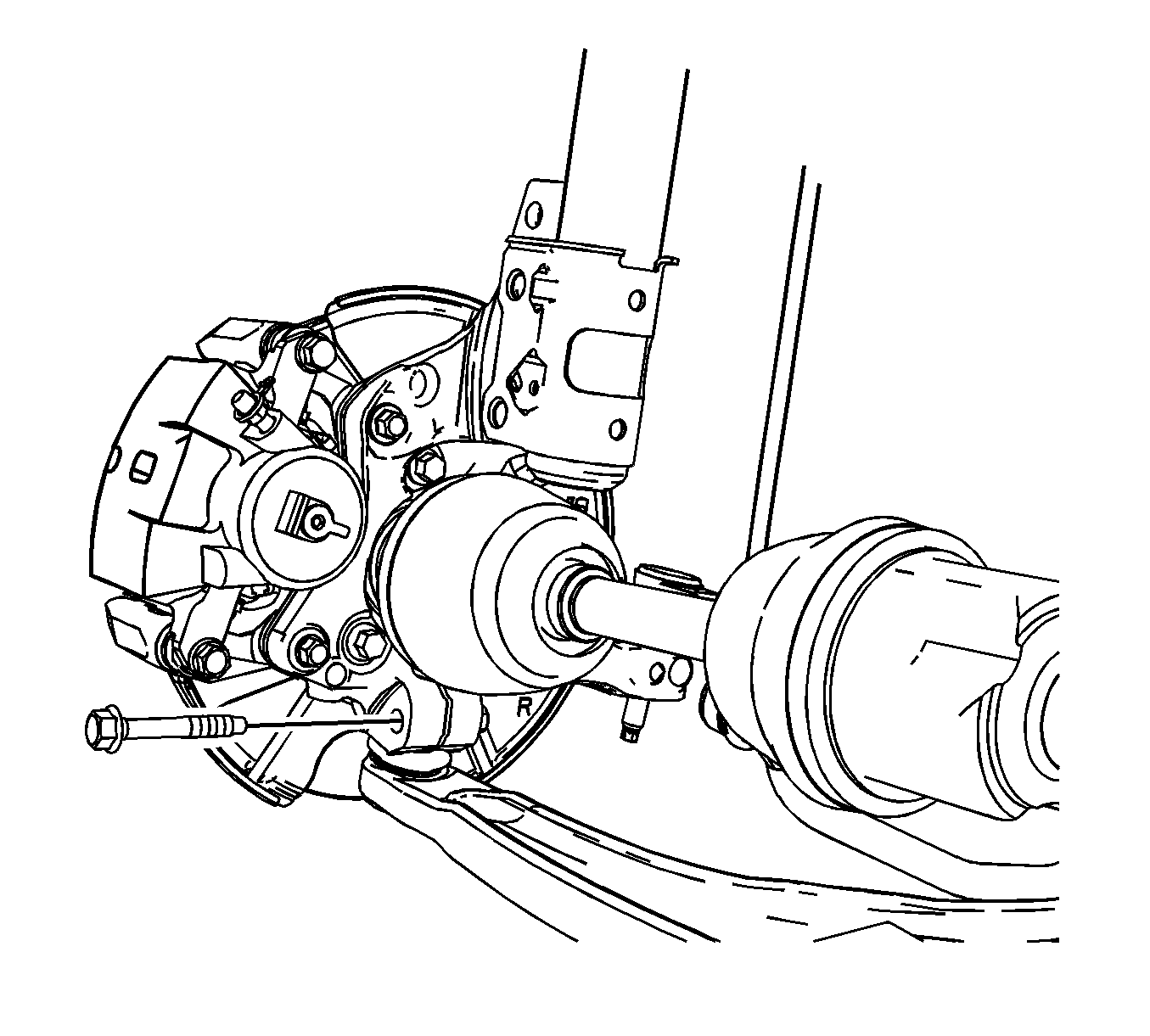
- Remove the wheel drive shafts from the transmission or the intermediate shaft only and move tie shafts out of the way. Refer to Wheel Drive Shaft Replacement.
- Lower the vehicle.
- Separate the ball stud from the steering knuckle.
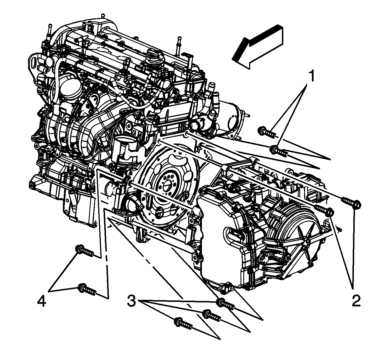
- Remove the engine mount to bracket bolts (1).
- Remove the transaxle mount to transaxle bolts.
- Raise the vehicle.
- Position a engine support table under the powertrain assembly.
- With the table positioned, fully raise the table to contact with the powertrain assembly.
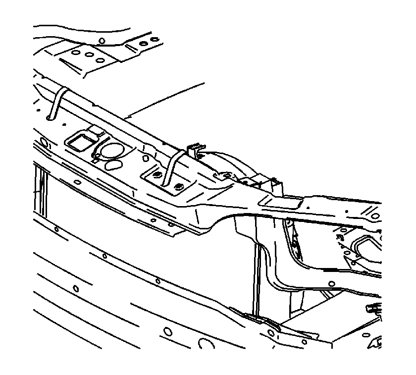
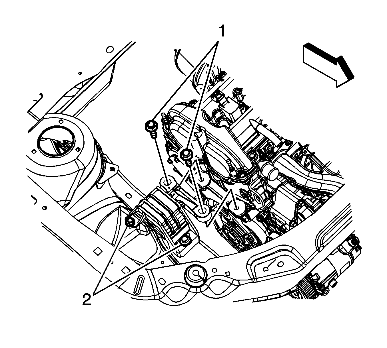
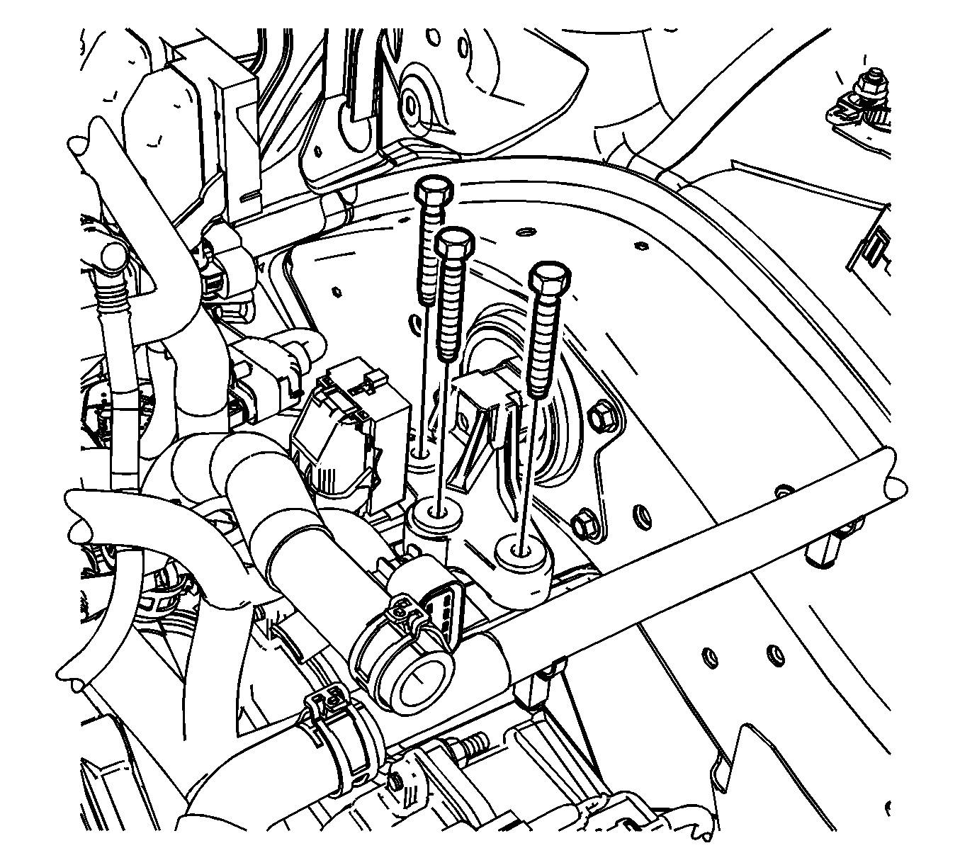
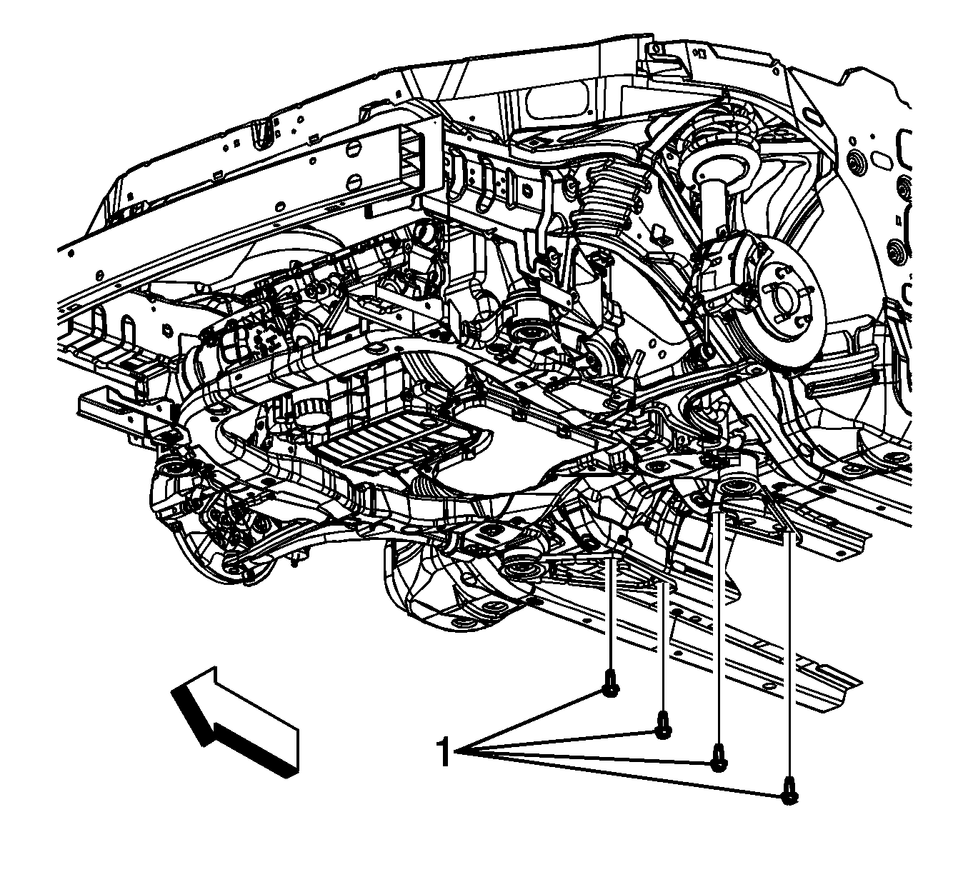
- Remove the frame to body bolts and the reinforcement brace bolts (1). Discard the bolts.
- Lower the engine table and raise the body on the hoist until the engine/transaxle and frame are free from the vehicle.
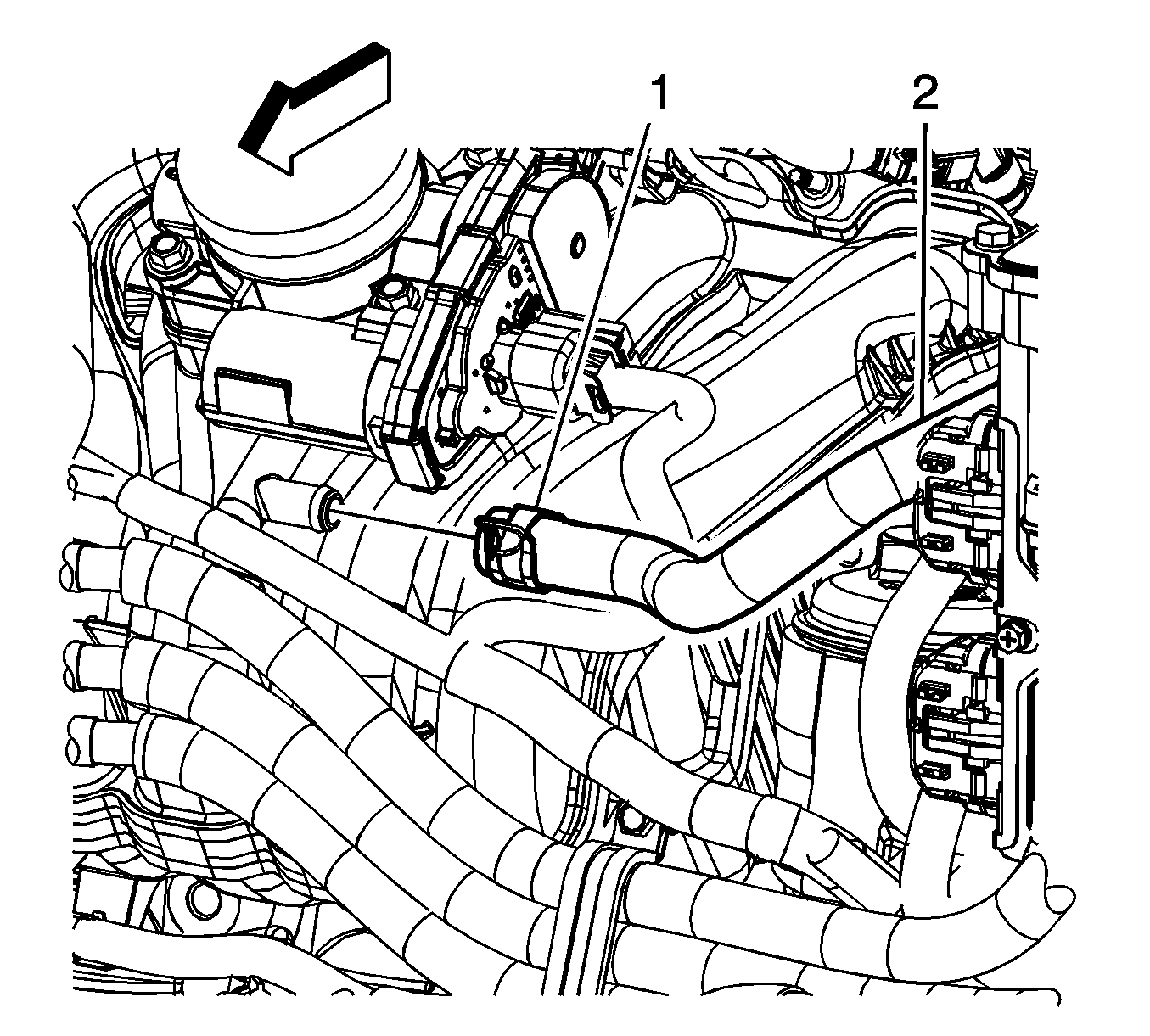
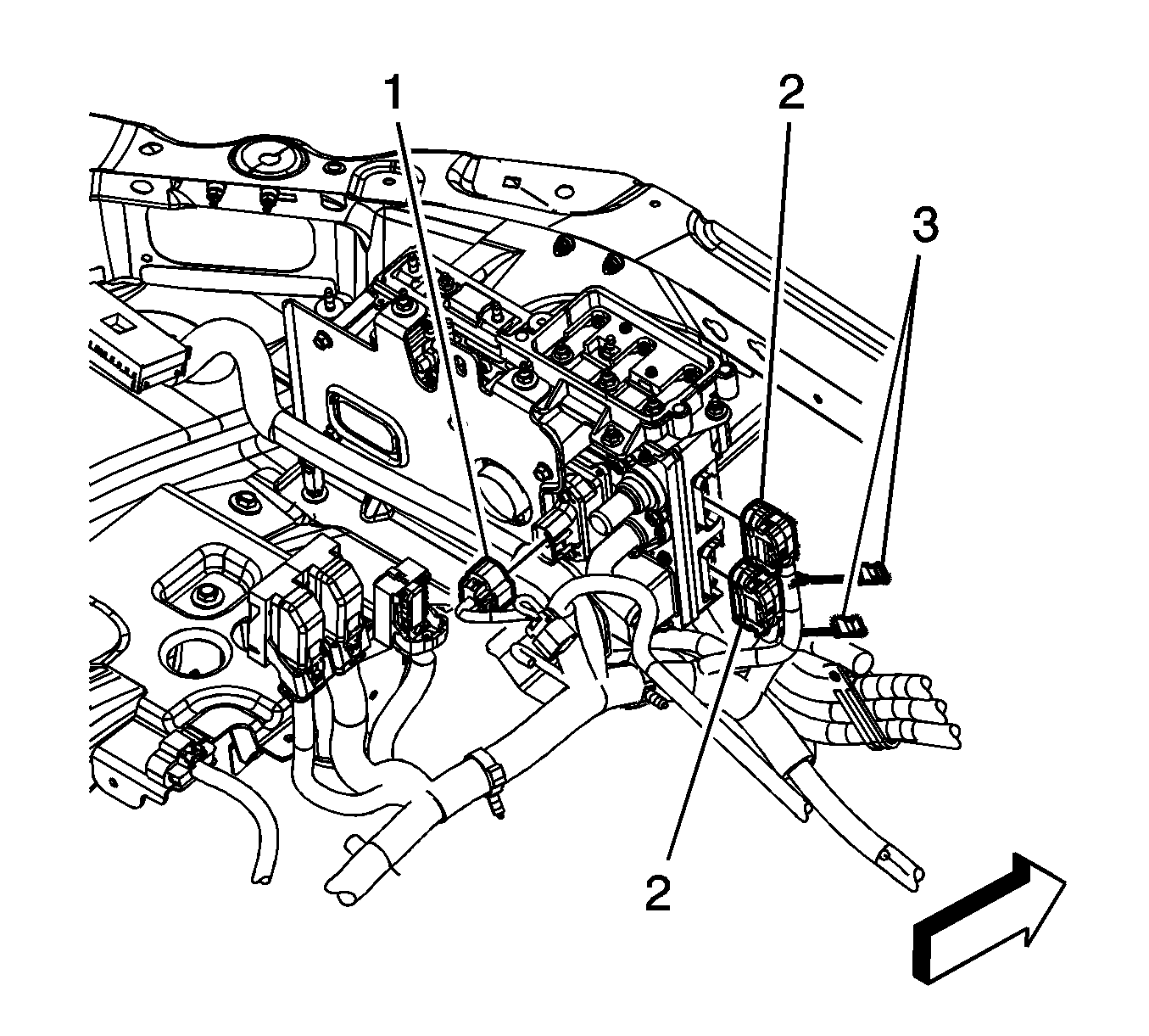
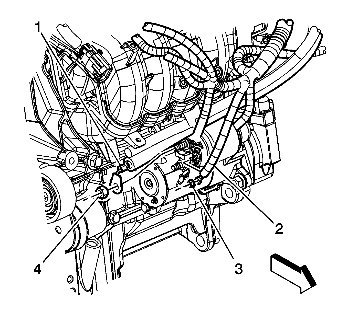
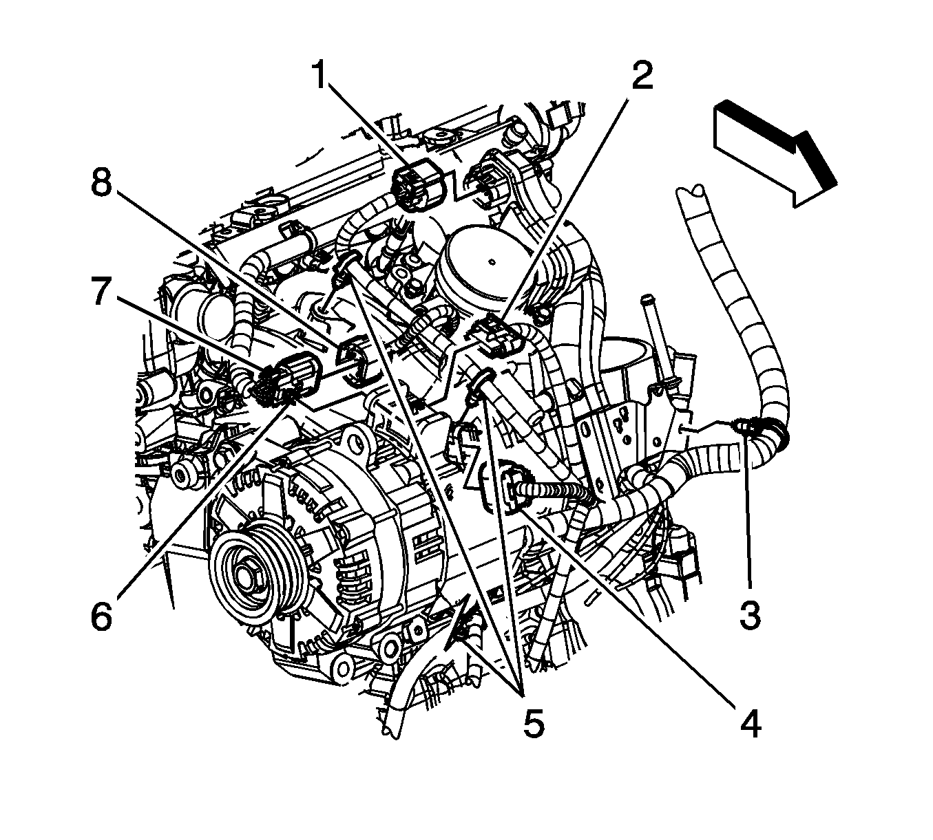
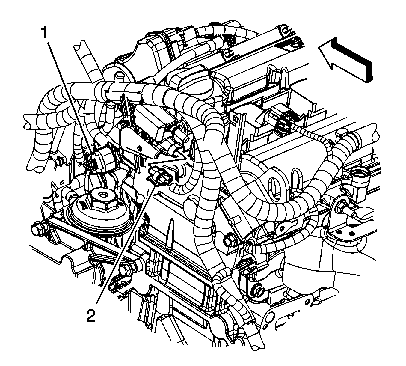
- Disconnect the engine wiring harness electrical connector (1) from the throttle actuator.
- Disconnect the engine wiring harness electrical connector (8) from the fuel injector wiring harness electrical connector (7).
- Remove the engine wiring harness clip (3) from the oil level indicator tube bracket.
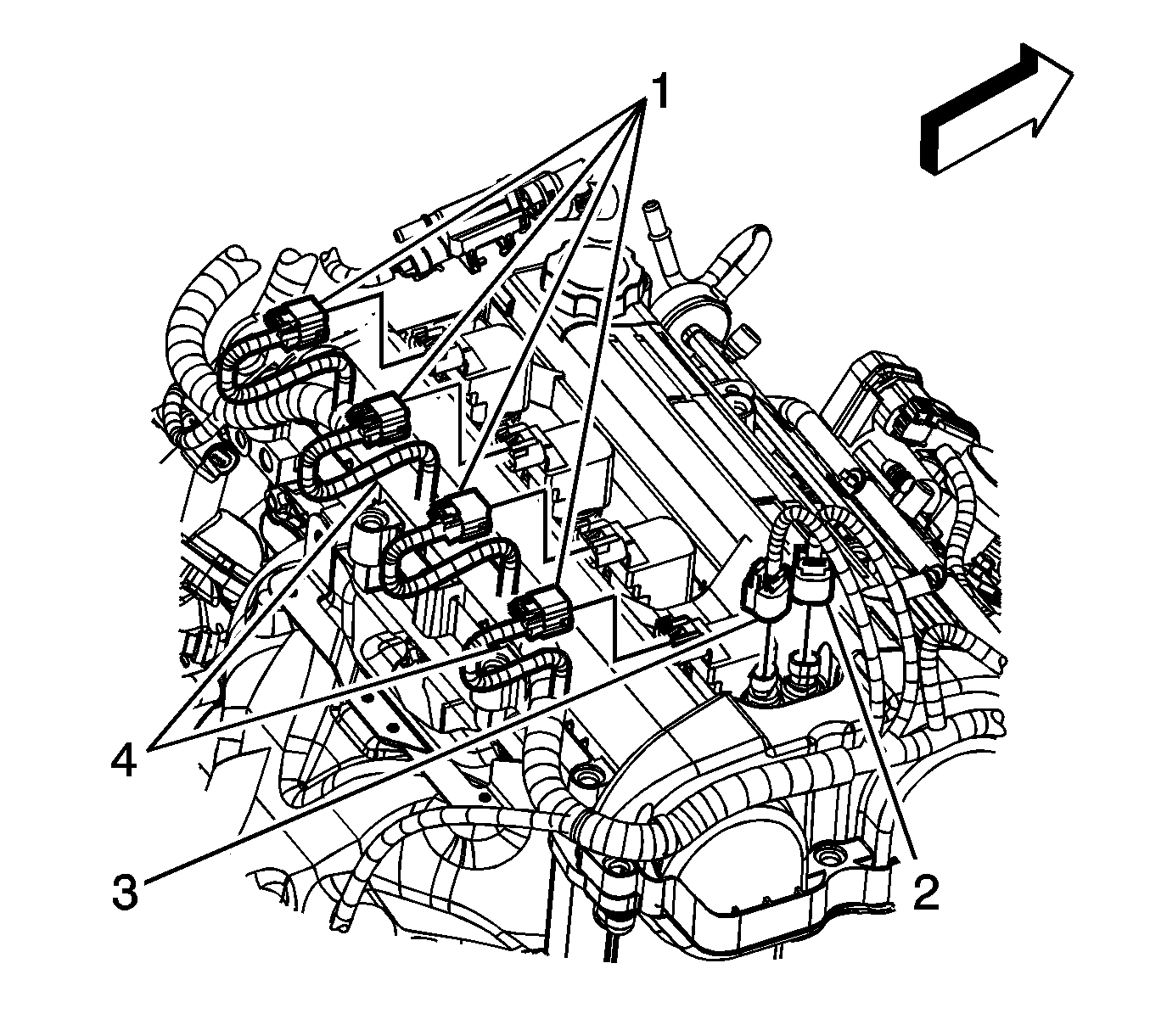
- Disconnect the engine wiring harness electrical connectors (1) from the ignition coils.
- Disconnect the engine wiring harness electrical connectors (2, 3) from the camshaft actuators.
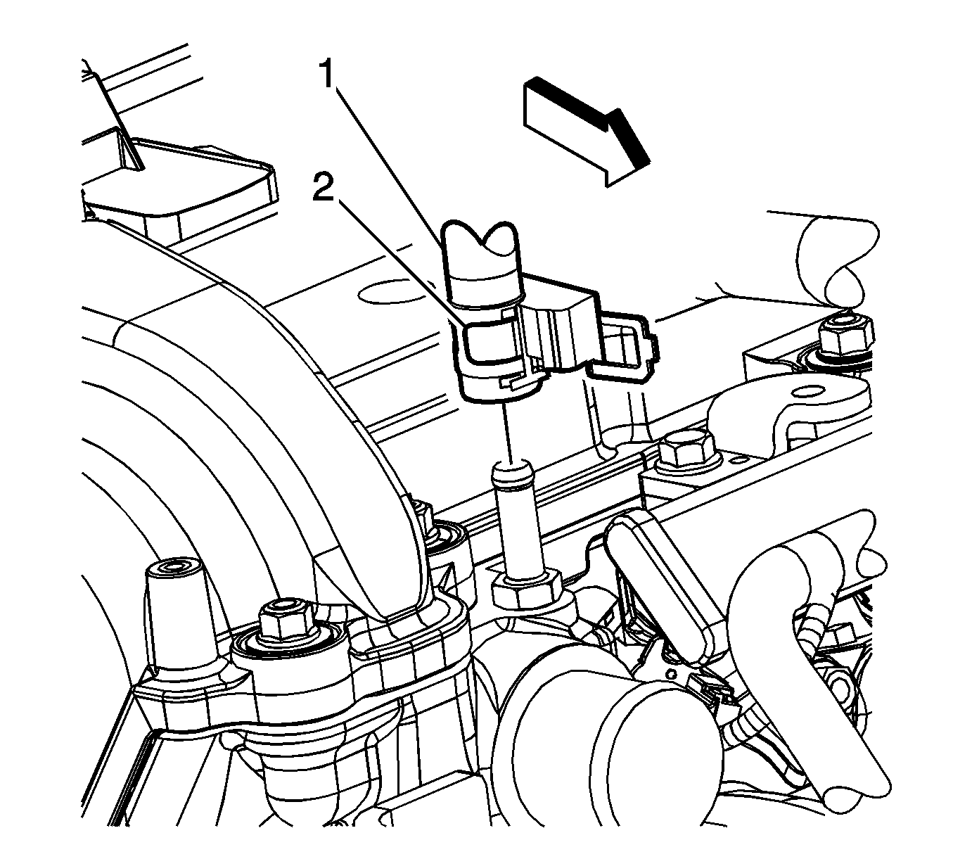
- Disconnect the engine wiring harness electrical connector (1) from the crankshaft position (CKP) sensor.
- Disconnect the engine wiring harness electrical connector (2) from the oil pressure sensor.
- Disconnect the engine wiring harness electrical connector (3) from the knock sensor.
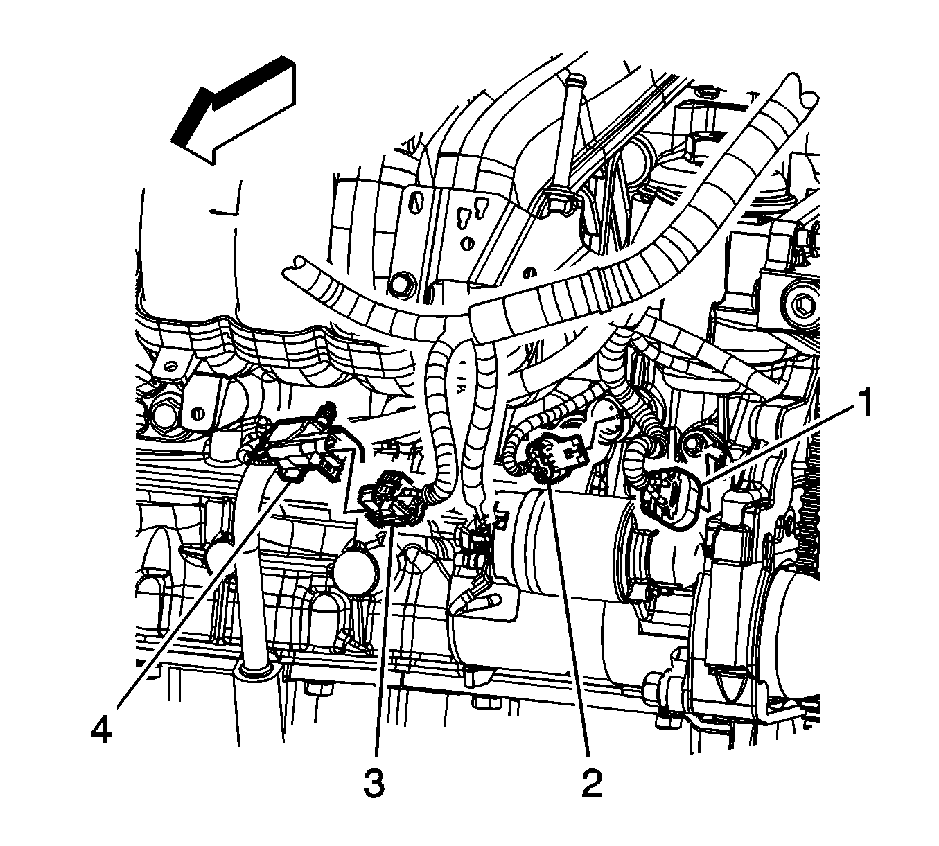
- Disconnect the engine wiring harness electrical connector (1) from the intake camshaft position (CMP) sensor.
- Disconnect the engine wiring harness electrical connector (2) from the EVAP emission canister purge solenoid valve.
- Disconnect the engine wiring harness electrical connector (1) from the exhaust CMP sensor.
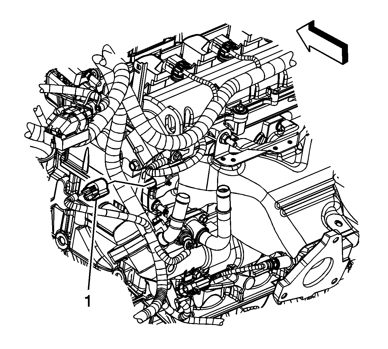
- Disconnect the engine wiring harness electrical connector (1) from the engine coolant temperature (ECT) sensor.
- Remove the engine wiring harness clip (5) from the stud.
- Remove the engine wiring harness ground bolt (1) and reposition the ground terminal from the engine.
- Gather all branches of the engine wiring harness and reposition the harness out of the way.
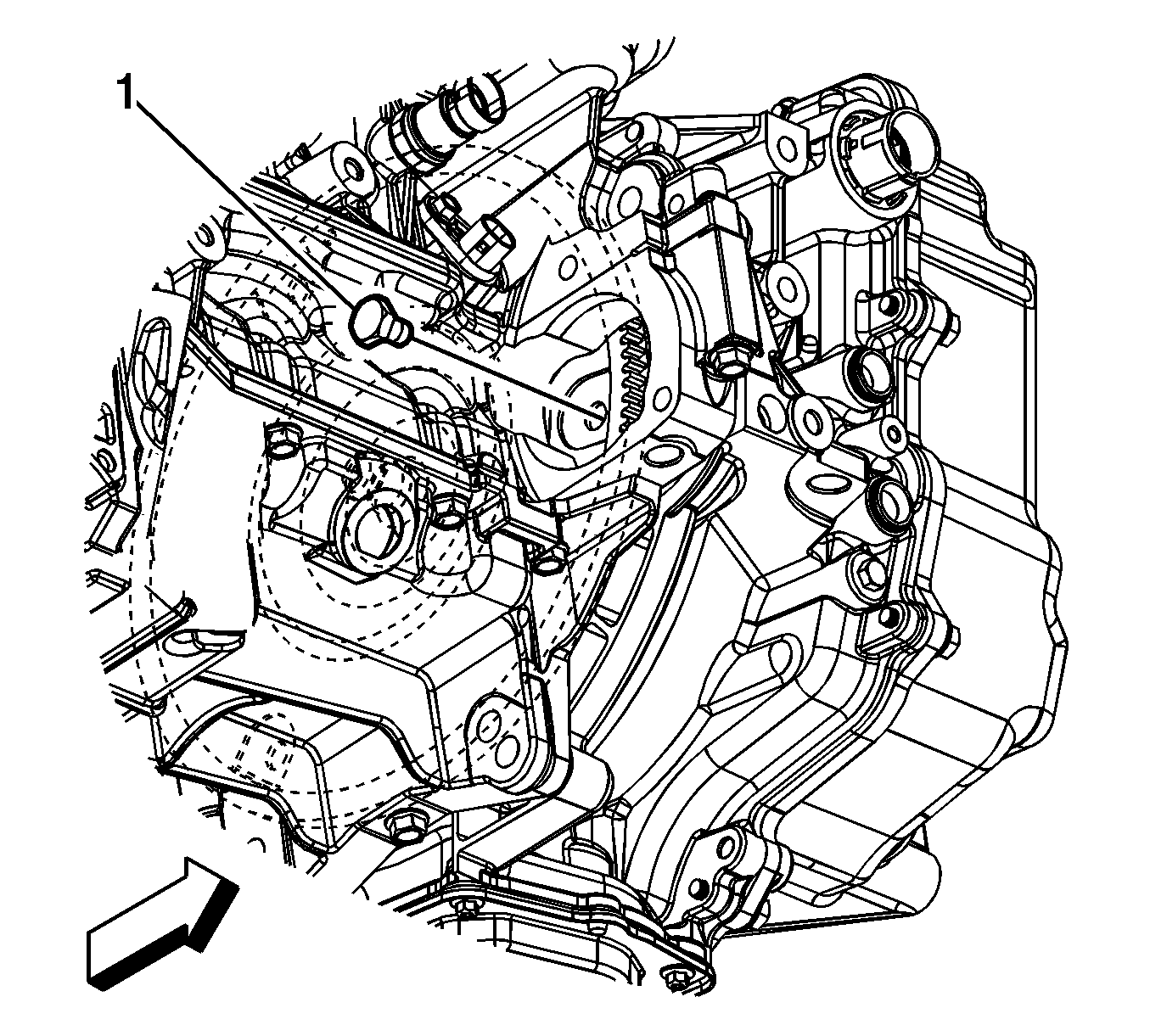
- Remove the starter motor bolts and starter.
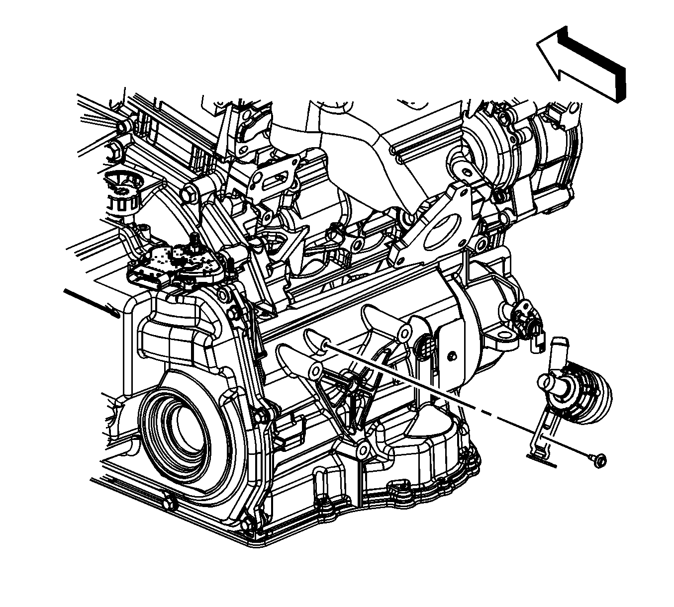
- Remove the torque converter to flexplate bolts (1).
- Install a suitable lifting devise to the engine.
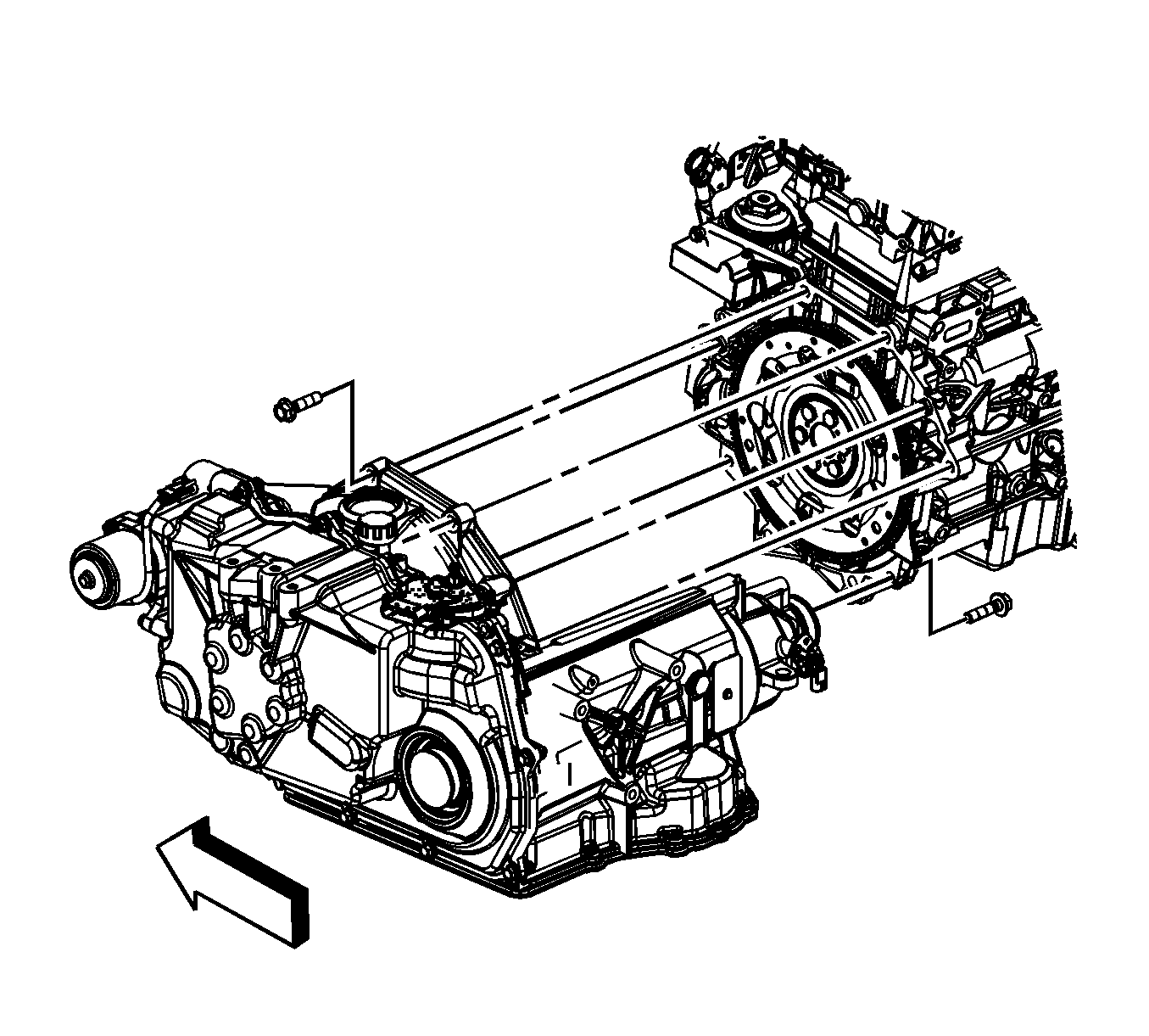
- If equipped with the 4T40, remove the transaxle brace.
- If equipped with the 4T40, remove the transaxle bolts from the engine.
- If equipped with the 6T40, remove the intermediate drive shaft. Refer to Wheel Drive Shaft Replacement.
- If equipped with the 6T40, remove the transaxle bolts (1, 2, 3, 4) from the engine.
- Separate the engine from the transaxle.
- Install the engine to a suitable engine stand.
- Transfer parts that are not furnished with new engine.
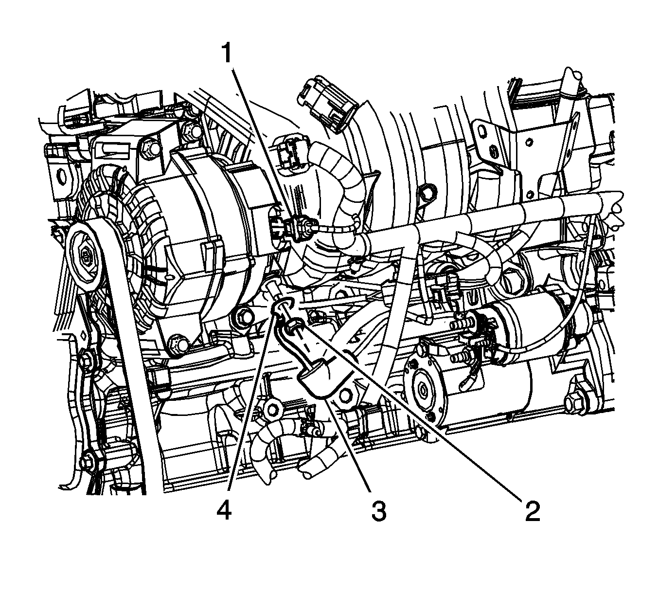
| 34.1. | Disconnect the generator electrical connector (1). |
| 34.2. | Reposition the engine harness boot (3). |
| 34.3. | Remove the generator nut (2). |
| 34.4. | Remove the engine harness lead (4) from the generator. |
Important: The radiator/condenser/fan assembly will stay in the vehicle during engine removal.
Important: A piece of hardwood should be used between the transaxle and the frame. This wood will support the engine when the left side engine mounts bolts are removed.
Important: A piece of hardwood should be used between the oil pan and the frame. This wood will support the engine when the right side engine mounts are removed.
Important: Secure the steering wheel in the straight forward position before separating the intermediate shaft from the steering gear, or damage to the SIR coil will occur.
Important: Hold the ball stud to prevent turning during removal of the nut.
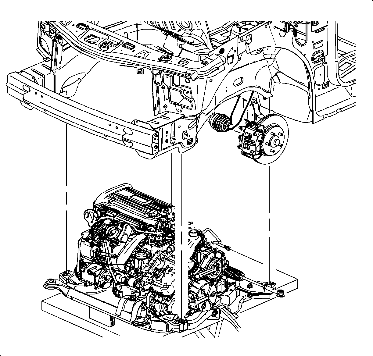
Important: During the powertrain removal support the vehicle body by placing a jack at the rear of the vehicle.
Important: Blocks of wood can be used between the front of the frame and the oil pan to table in order to level the powertrain during the removal.
Important: When lowering the engine/transaxle assembly, verify all brake lines, shifter cables and other components are free during removal.
Installation Procedure
- Install a suitable lifting devise to the engine.
- Using the lifting devise, position and install the engine to the transaxle.
- If equipped with the 4T40, install the transaxle brace.
- If equipped with the 4T40, install the transaxle bolts to the engine.
- If equipped with the 6T40, install the transaxle bolts to the engine.
- Install the torque converter to flexplate bolts (1).
- Remove the engine lifting devise.
- Install the starter motor and bolts.
- Gather all branches of the engine wiring harness and position the harness to the engine.
- Position the engine wiring harness ground terminal to the engine and install the engine wiring harness ground bolt (1).
- Connect the engine wiring harness electrical connector (1) to the ECT sensor.
- Install the engine wiring harness clip (5) to the stud.
- Connect the engine wiring harness electrical connector (1) to the exhaust CMP sensor.
- Connect the engine wiring harness electrical connector (1) to the intake CMP sensor.
- Connect the engine wiring harness electrical connector (2) to the EVAP emission canister purge solenoid valve.
- Connect the engine wiring harness electrical connector (1) to the CKP sensor.
- Connect the engine wiring harness electrical connector (2) to the oil pressure sensor.
- Connect the engine wiring harness electrical connector (3) to the knock sensor.
- Connect the engine wiring harness electrical connectors (1) to the ignition coils.
- Connect the engine wiring harness electrical connectors (2, 3) to the camshaft actuators.
- Connect the engine wiring harness electrical connector (1) to the throttle actuator.
- Connect the engine wiring harness electrical connector (8) to the fuel injector wiring harness electrical connector (7).
- Install the engine wiring harness clip (3) to the oil level indicator tube bracket.
- Position the powertrain and support table under the vehicle.
- Raise the powertrain into position under the vehicle.
- With the table positioned, if required, lower the vehicle over the powertrain.
- Align the lower radiator pins with the frame. Ensure all hoses and electrical harnesses are correctly routed and free from the loading path of the powertrain.
- Install the NEW frame to body bolts.
- Install the frame reinforcements and bolts (1).
- Lower the vehicle.
- Install the transaxle mount to transaxle bolts.
- Install the engine mount to bracket bolts (1).
- Raise and support the vehicle.
- Install the wheel drive shafts to the transmission or intermediate shaft. Refer to Wheel Drive Shaft Replacement.
- Note the previous orientation and install a new ball stud to the steering knuckle pinch bolt.
- Tighten the ball stud to steering knuckle pinch nut to 50 N·m (37 lb ft).
- Reverse the nut 3/4 of a turn.
- Tighten to 50 N·m (37 lb ft)
- Using the J 45059 , rotate an additional 30 degrees.
- Continue to tighten the nuts only enough to align the castle nut slots with the ball stud, install NEW cotter pins.
- Connect the stabilizer links to the stabilizer shaft and install the stabilizer link to stabilizer shaft nuts.
- Connect the outer tie rods to the steering knuckles.
- Use the J 44015 in order to seat the ball stud taper to 40 N·m (30 lb ft).
- Remove the J 44015 .
- Install NEW outer tie rod to steering knuckle nuts.
- Position the intermediate shaft to the steering gear and install a NEW pinch bolt.
- Install the exhaust manifold. Refer to Exhaust Manifold Replacement.
- If equipped with the 4T45, install the transaxle oil cooler lines to the transaxle.
- If equipped with the 4T45, install the transaxle oil cooler line to transaxle nut (1).
- If equipped with the 6T40, install the fluid cooler lines at the transaxle. Refer to Fluid Cooler Inlet Hose Replacement and Fluid Cooler Outlet Hose Replacement.
- Remove the wood from between the oil pan and the frame.
- Remove the wood from between the transaxle and the frame.
- Install the left and right engine splash shields.. Refer to Engine Splash Shield Replacement - Left Side and Engine Splash Shield Replacement - Right Side.
- Install the front wheels and tires. Refer to Tire and Wheel Removal and Installation.
- Lower the vehicle.
- Unsecure and position the radiator/condenser/fan assembly.
- Install the shift control cable to the shift control cable bracket and engage the shift control cable retaining clip.
- Install the transaxle shift cable to the range select lever.
- Raise and support the vehicle.
- LAT only, install the auxiliary heater water pump and bolt.
- Install the negative battery cable to the engine stud.
- LAT only, connect the engine wiring harness electrical connector (2) to the auxiliary heater water pump.
- LE5 only:
- Position and install the positive battery cable between the starter and the engine.
- Install the positive battery cable lead (1) to the starter motor.
- Install the positive battery cable to starter motor nut (4).
- Position the A/C compressor and install the bolts.
- LAT only, install the generator control module coolant pump (2) and bolt (3).
- LAT only, connect the engine wiring harness electrical connector (1) to the generator control module coolant pump.
- Connect the engine wiring harness electrical connector (2) to the A/C compressor.
- Lower the vehicle.
- Install the coolant recovery reservoir/heater inlet hose (4) to the thermostat housing.
- Position the coolant recovery reservoir/heater inlet hose clamp (3) at the thermostat housing.
- Install the heater inlet hose (3) to the thermostat housing.
- Position the heater inlet hose clamp (1) at the thermostat housing.
- LAT only, connect the engine wiring harness electrical connector (1) to the transaxle auxiliary pump module.
- LAT only, install the generator control module coolant hose to the generator control module.
- LAT only, position the generator control module coolant hose clamp (1) at the generator control module.
- Reposition the radiator inlet hose clamp using the J 38185 .
- Remove the radiator inlet hose from the cylinder head.
- Remove the radiator outlet hose. Refer to Radiator Outlet Hose Replacement.
- Position and install the coolant recovery inlet hose (1) to the cylinder head.
- Install the coolant recovery inlet pipe clip to the fuel rail.
- Install the coolant recovery inlet hose clamp (2) at the cylinder head.
- Position and install the vacuum brake booster hose (2) to the intake manifold.
- Position the vacuum brake booster hose clamp (1) at the intake manifold.
- Install the generator starter. Refer to Generator with Starter Replacement.
- Install the battery tray. Refer to Battery Tray Replacement.
- Install the fuel feed pipe clip (2) to the fuel line bracket.
- Connect the EVAP line (3) quick connect fitting to the EVAP purge solenoid. Refer to Plastic Collar Quick Connect Fitting Service.
- Connect the fuel feed pipe (1) quick connect fitting at the fuel rail. Refer to Metal Collar Quick Connect Fitting Service.
- Install the air cleaner assembly. Refer to Air Cleaner Assembly Replacement.
- Install the air cleaner outlet duct. Refer to Air Cleaner Outlet Duct Replacement.
- Fill the transaxle with fluid. Refer to Transmission Fluid Check or Transmission Fluid Check.
- Refill the engine with oil. Refer to Engine Oil and Oil Filter Replacement.
- Perform the CKP system variation learn procedure. Refer to Crankshaft Position System Variation Learn.
- Start the engine and allow the engine to run, inspect for leaks. Correct as necessary.
Notice: Refer to Fastener Notice in the Preface section.
Tighten
Tighten the bolts to 75 N·m (55 lb ft).
Tighten
Tighten the bolts to 75 N·m (55 lb ft).
Tighten
Tighten the bolts to 60 N·m (44 lb ft).
Tighten
Tighten the bolts to 53 N·m (39 lb ft).
Tighten
Tighten the bolt to 20 N·m (15 lb ft).
Tighten
Tighten the bolts to 100 N·m (74 lb ft) plus rotate 90 degrees.
Tighten
Tighten the bolts to 50 N·m (37 lb ft).
Tighten
Tighten the bolts to 55 N·m (41 lb ft).
Important: The engine mount to bracket bolts must be hand started. Do not pry the engine mount to align the holes.
Tighten
Tighten the bolts to 50 N·m (37 lb ft).
Tighten
Tighten
Tighten the nuts to 65 N·m (48 lb ft).
Tighten
Tighten the nuts to 25 N·m (48 lb ft) plus 90 degrees.
Tighten
Tighten the bolt to 34 N·m (25 lb ft).
Tighten
Tighten the nut to 4 N·m (27 lb in).
Tighten
Tighten the bolt to 9 N·m (80 lb in).
Tighten
Tighten the nut to 25 N·m (18 lb ft).
| 59.1. | Install the engine harness lead (4) to the generator. |
| 59.2. | Install the generator nut (2). |
Tighten
Tighten the nut to 20 N·m (15 lb ft).
| 59.3. | Seat the engine harness boot (3). |
| 59.4. | Connect the generator electrical connector (1). |
Tighten
Tighten the nut to 9 N·m (80 lb in).
Tighten
Tighten the bolts to 50 N·m (37 lb ft).
Tighten
Tighten the bolt to 25 N·m (18 lb ft).
