For 1990-2009 cars only
Special Tools
J 45059 Angle Meter
Removal Procedure
- Raise and support the vehicle. Refer to Lifting and Jacking the Vehicle.
- Remove the rear tire and wheel assembly. Refer to Tire and Wheel Removal and Installation.
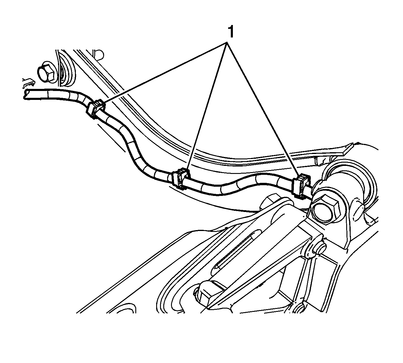
- Disconnect the wheel speed sensor wiring harness retaining clips (1) and relocate to the side.
- Remove the rear muffler from the hangers and lower the muffler to gain access to the upper control arm nut and bolt. Refer to Muffler Replacement.
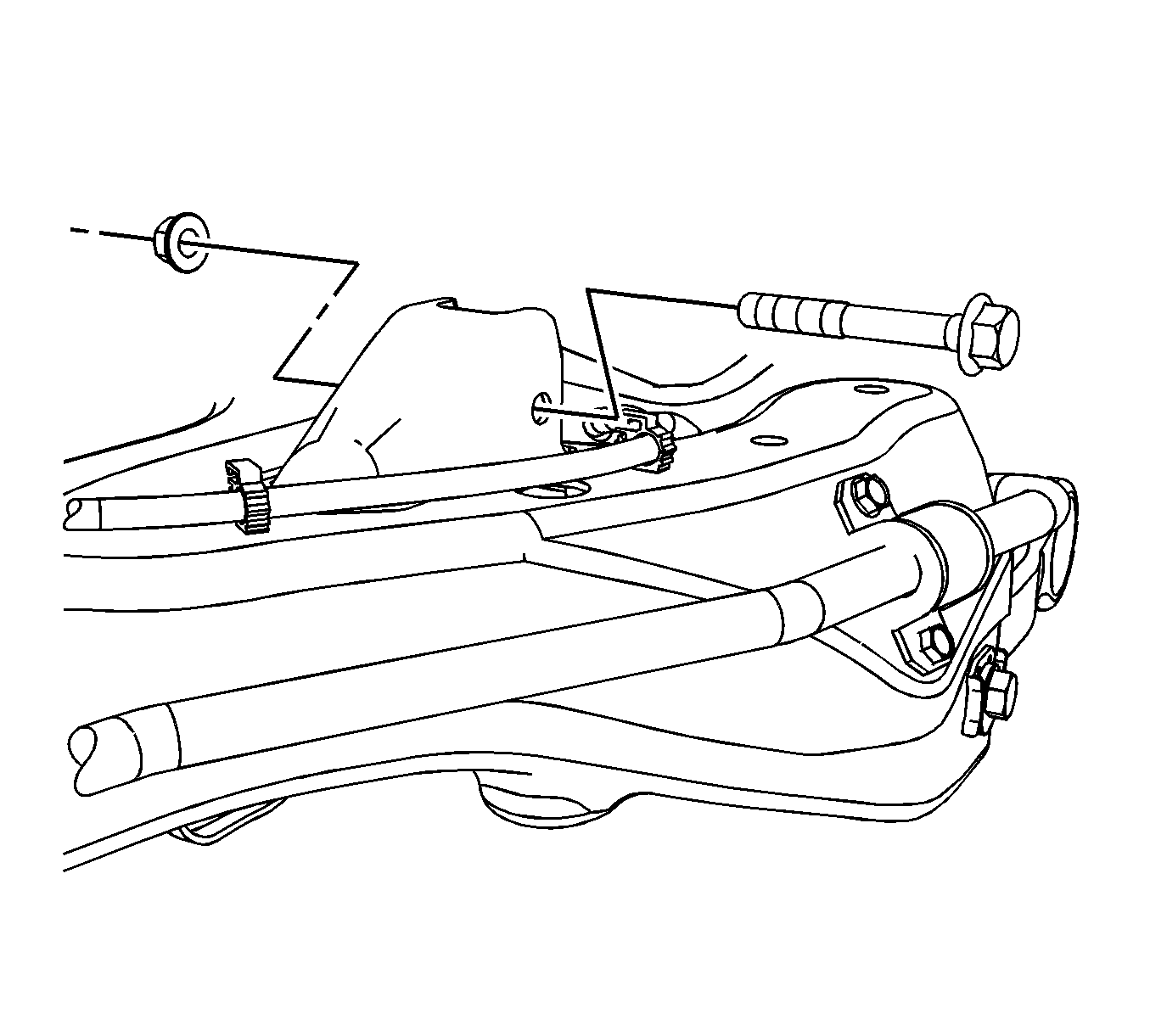
- Remove the upper control arm assembly nut and bolt from the rear support.
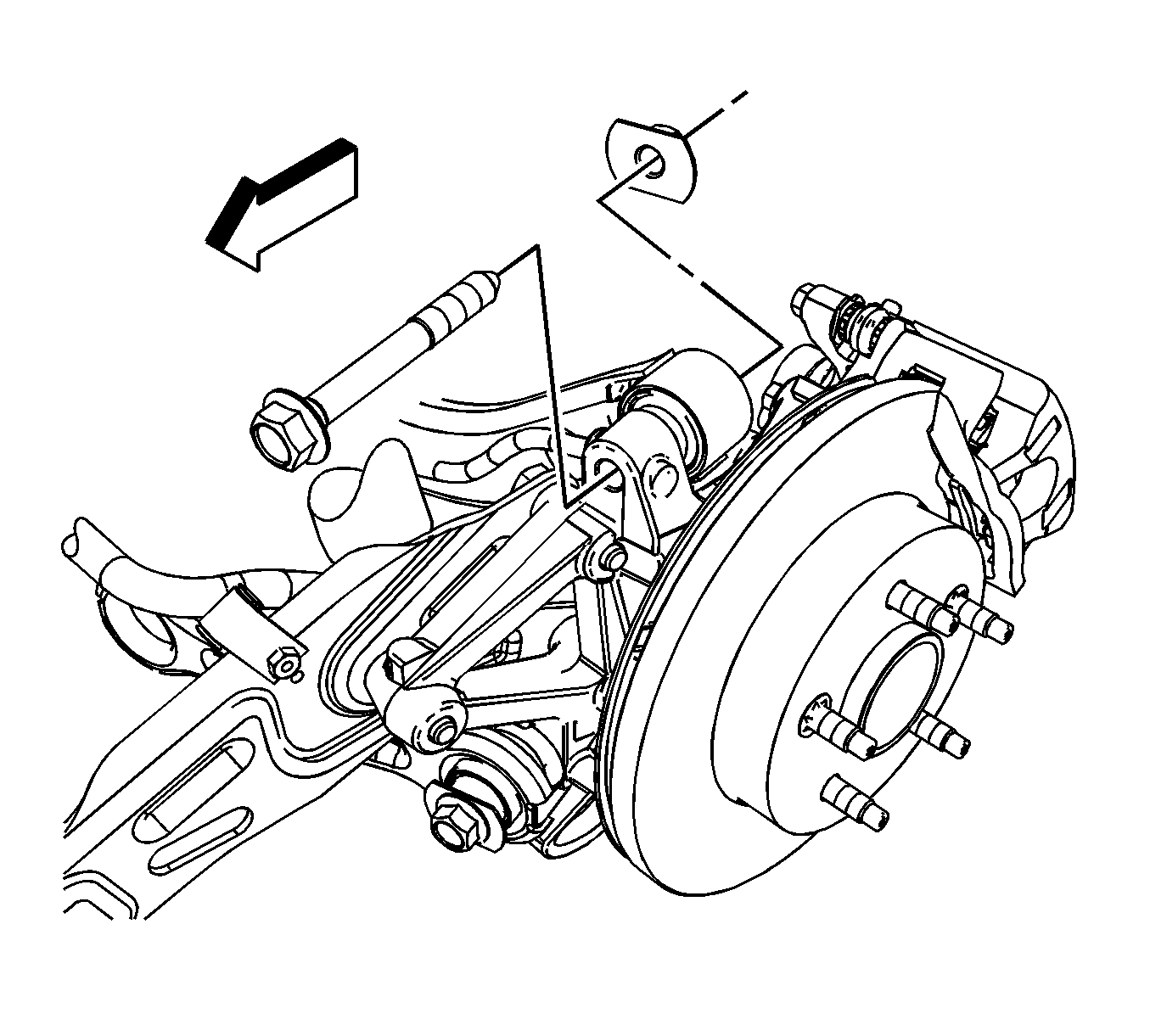
- Remove the upper control arm nut and bolt from the knuckle.
- Remove the upper control arm from the vehicle through the wheelhouse opening.


Important: Note the that the head of the bolt is facing the front of the vehicle and must be install in the same position.

Installation Procedure
- Install the upper control arm in the support.
- Install the upper control arm nut and bolt.
- Install the upper control arm nut and bolt in the knuckle.
- Reposition the wheel speed sensor wiring harness retaining clips (1) on the upper control arm.
- Install the rear muffler. Refer to Muffler Replacement.
- Install the rear tire and wheel assembly. Refer to Tire and Wheel Removal and Installation.
- Lower the vehicle.

Notice: Refer to Fastener Notice in the Preface section.
Tighten
Tighten the upper control arm to support assembly nut to 60 N·m (44 lb ft). Using the
J 45059
, rotate an additional 60 degrees.

Tighten
Tighten the upper control arm to knuckle nut to 110 N·m (81 lb ft). Using the
J 45059
, rotate an additional 70 degrees.

