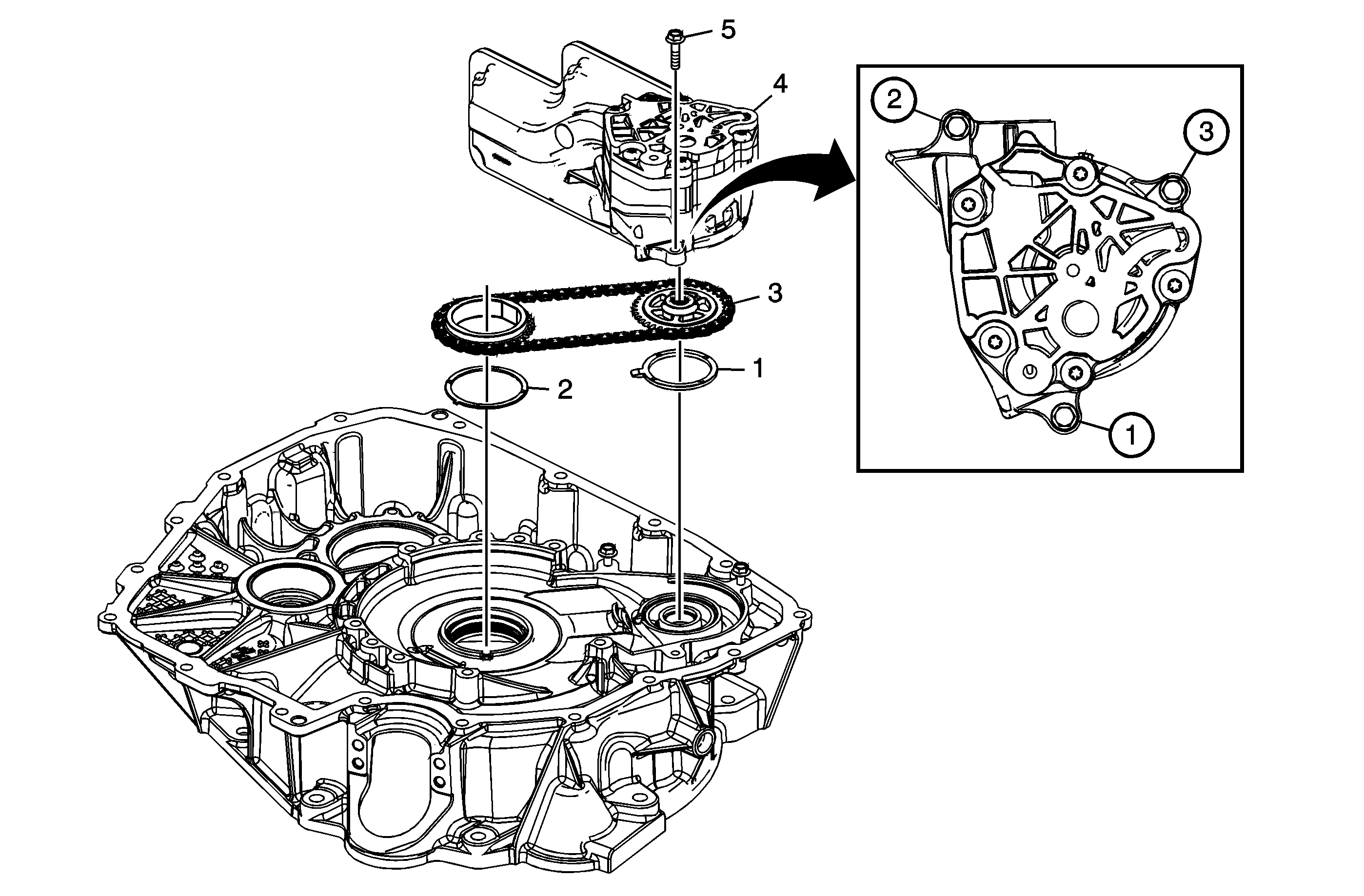
| Table 1: | Pump Assembly Installation |
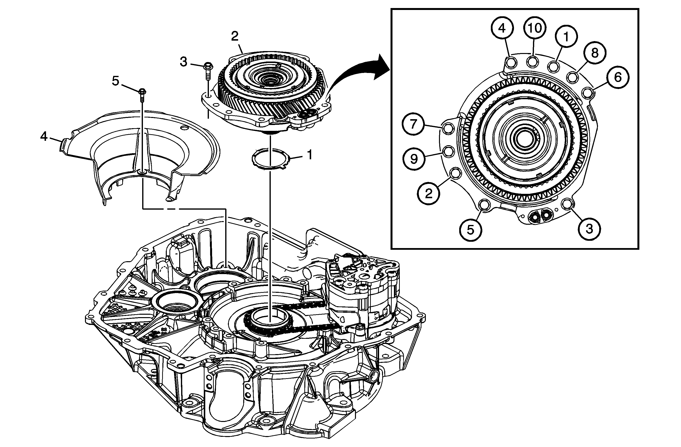
| Table 2: | Transfer Drive Gear Assembly Installation |
Pump Assembly Installation

Callout | Component Name |
|---|---|
1 | Driven Sprocket Thrust Washer |
2 | Drive Sprocket Thrust Washer |
3 | Install Drive Link Assembly Tip |
4 | A/Trans Fluid Pump Assembly Tip |
5 | A/Trans Fluid Pump Bolt M6 x 25 (Qty: 3) Notice: Refer to Fastener Notice in the Preface section. Procedure:Tighten in sequence shown. Tighten |
Transfer Drive Gear Assembly Installation

Callout | Component Name |
|---|---|
1 | Drive Sprocket Thrust Washer |
2 | Front Differential Transfer Drive Gear Support Assembly |
3 | Front Differential Transfer Drive Gear Support Bolt M8 x 25 (Qty: 10) Notice: Refer to Fastener Notice in the Preface section. ProcedureTighten in sequence shown. Tighten Special Tools:J 45059 Angle Meter |
4 | Front Differential Carrier Baffle |
5 | Front Differential Carrier Baffle Bolt M6 x 25 Tighten |
